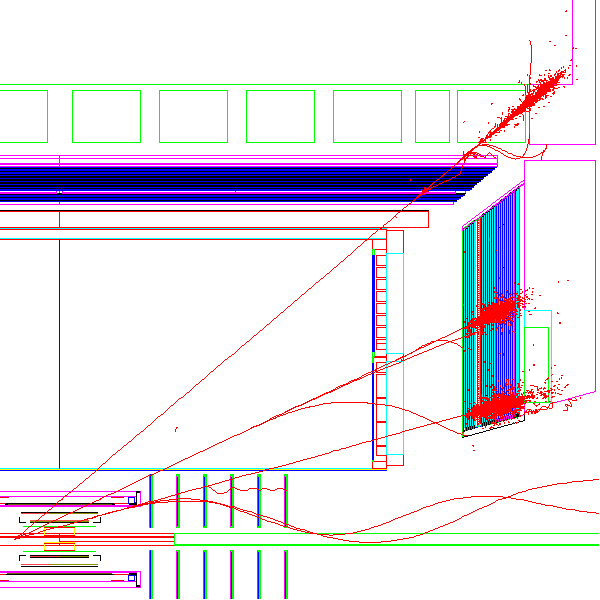
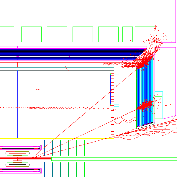
Generated electrons have fixed pT and zVertex of -30, 0, or +30 cm, and uniform eta and phi distribution. Sample of high pT electrons thrown from different zVertex location over eta range [1,2] are shown here: Z=-30cm , Z=0cm , Z=+30cm ,
Combined 3Z locations:

The plot shows 9 electrons with fixed pT=40 GeV/c, Z={-30,0,+30}cm, and eta={1.0,1.5,2.0}
* Use: Vertex, IST1+2, SSD, 6-disk FGT, truncated TPC(nHit>=5), ESMD
| detector | assumed resolution | weight of the point | Remarks |
|---|---|---|---|
| vertex | 200 mu m in X,Y 30 cm in Z | W=1/(200 mu m)^2 | added as a hit |
| IST1 | 20 mum in r*phi 0.5 mm in Z | W=1/(20 mu m)^2 | - |
| IST2 | 0.5 mm in r*phi 20 mum in Z | W=1/(0.5 mm)^2 | - |
| SSD | 20 mum in r*phi 1 mm in Z | W=1/(20 mu m)^2 | - |
| FGT | 60 mu m in X,Y 1 mm in Z | W=1/(60 mu m)^2 | 6 disks hit reco eff=100% |
| TPC | 1 mm along arc 1 mm in Z | W=1/(1mm)^2 | * drop padrow #1 and #13 * drop hits at |Z|>197 cm * drop all hits if below 5 |
| Endcap SMD
mock hit **) | 1.5 mm in X,Y 5mm in Z | W=1/(1.5 mm)^2 | at xPoint of Geant helix w/ SMD plane |
**) Based on SMD response study by Jim

    CONFIG
         A :  default
         B :  no IST, no SSD
         C :  only TPC+SMD+VERT
         D :  no IST, no SSD, variable FGT(Z)
Track reco efficiency is defined as the ratio of# of reco tracks (N1) w/
* nFitP>=5, including vertex as a hit
* delPhi<3 mrad
* delTheta <3 mrad
to the # of generated electrons (N0).
Charge reco efficiency requiers additinal
* the sign of the reco charge is correct. Track counter is N2.
No cut on reco pT is imposed.
Note, we do not want to be in the magenta sqare.
| track Eff= N1/N0 | charg eff = N2/N0 | wrong charge (N1-N2)/N1 | Geant Pt - Reco Pt , matched in delEta & delPhi |
|---|---|---|---|
| Config A : all in: Vertex, IST1+2, SSD, FGT, TPC , ESMD | |||

| 
| 
| 
|
| Config B : drop IST, drop SSD | |||

| 
| 
| 
|
| Config C : use only TPC+ESMD+Vertex | |||

| 
| 
| 
|