|
TOFp Local Trigger User's Guide
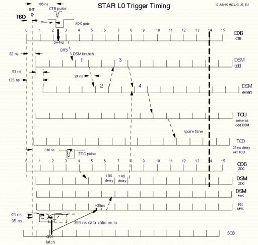
STAR Level-0 Timing Diagram:
Local Trigger Logic Diagram:
Timing Diagrams, "normal" running:
Timing Diagrams, "pulser" running:
|
|
This is a note to try to clarify some points regarding the interaction
of the TOFp Trigger and TOFp DAQ with the STAR TRG and STAR DAQ, as well
as the interaction of the TOFp Trigger and TOFp DAQ. The problem that we were most concerned about during the week of 9 April 2001 when I was at BNL was the potential for missing transmissions from STAR TRG, particularly L2 Accept. The problem arises because the BiRa 2601 I/O Register can only accept one input word at a time. If a word (L0, L2 Accept, or Abort) has been stored but not read out, and another is strobed in, the first word is lost. Because we can only control the transmission of L0 data from the TCD this gives some possibility that transmissions can be missed as discussed below. We have known about this problem for a long time. However, until recent discussions, particularly with Tonko Ljubicic, I was not aware of the consequences of missing a L2 Accept. Basically, if a L2 Accept is missed and we don't respond with data (real or fake), the STAR DAQ will wait for us for up to 5 seconds. Obviously, this isn't a problem if it only happens occasionally. However, if we cause such a timeout often and impact the live time of the experiment, STAR DAQ will simply remove us from the system. Also, until talking with Zhixu and Frank, I hadn't quite realized that reading out an event would take 900 micro-s (as the DAQ is currently set up) and that we would be unable to respond to interrupts during this time since we are doing DMA. It is during this readout time when L2 confusion is likely to occur. STAR Information STAR TRG timing - I have attached a STAR L0 Trigger Timing diagram (star-l0-timing.ps) from the STAR TRG web site and some of the discussion relates to this diagram. I have had a number of discussions with the Trigger group and I think I now have an accurate picture of what happens in the STAR Trigger. I apologize for repeating information that may be familiar to some of you. Note that the TCU clock is delayed w.r.t. the CDB clock by 82 ns. The TCD is further delayed by 51 ns from the TCU. The first TCU clock edge shown is delayed from the CDB "0" edge by 82 ns. I will refer to this as the TCU 0 edge. The TCU makes its trigger decision in the interval between the TCU 9 and 10 clock edges. Part of the decision involves which detectors are active. Thus, the TCU incorporates a latch that holds information on which detectors are alive, transmitted from their respective TCD units. TCD DAQ BUSY - The TCD has a front panel input that accepts a busy signal. As currently implemented, the signal is an OR of a STAR DAQ BUSY and the TOF System BUSY generated by the TOFp trigger. When asserted, the TCD DAQ BUSY is used by the TCU (see below) to identify the active subsystems and inhibits the transmission of L0 Triggers. It does not directly inhibit the transmission of L2 Accept or Abort. If the TCD DAQ BUSY for TOF is present when a L0 is generated then the detector bitmask used by TRG to determine which detectors were active in an event will show TOF busy and higher level trigger commands (L1, L2, Abort) for that event will not be sent to TOF. TCU latch of TCD DAQ BUSY - The TCD transmits BUSY signals applied to its front panel DAQ BUSY input via analog lines (not clocked). These are latched on the TCU 9 clock edge. This comes between about 935 ns and 1041 ns after the collision (assuming a 106.59 ns RHIC clock cycle) depending on when within a RHIC cycle the collision occurs and the phase adjustment of the CDB clock. The TOF System Busy (see discussion below) must not be asserted at this point after a locally triggered event so that if a L0 Trigger is generated by STAR TRG, it will not be blocked. The TOFp logic is configured to drop the TOF System BUSY to the TCD in this interval. L0 Trigger - If a L0 Trigger is generated (and not vetoed by the TCD DAQ BUSY) then it is sent from the TCU on the TCU 10 clock edge. The L0 is received by the TCD and sent out one clock cycle later. Since the TCD lags the TCU by 51 ns, L0 is sent between approximately 1200 ns and 1306 ns after the collision. The TOFp logic is configured to look for a coincidence between L0 and the TOFp TRIG in this interval to validate the event. L1 Trigger - L1 Triggers are not implemented for 2001. The L1 Trigger is intended to define events as accepted for L2 analysis. When implemented, it is expected that L1 will take about 100 micro-s. L2 Accept - If a L0 Trigger is generated by STAR TRG then either a L2 Accept or an Abort with a corresponding token is generated after higher level trigger decisions have been made. The L2 or Abort has to follow the L0 in time. The TOFp Trigger does not receive information from the TCD that a L2 transmission has been sent and cannot block transmission of L2 Accept or Abort. All L2 information must be acquired through the TOFp DAQ (using the BiRa 2601). In principle, a L2 Accept can be generated at any time following a L0 decision. However, the specification for L2 says that it should be generated within 10 ms. Practical considerations seem to dictate that L2 will take at least 1 ms, but this is not part of the specification. On receipt of a L2 Accept, the TOFp DAQ must ship event data to STAR DAQ. This is done entirely with a "push" architecture in which the TOFp DAQ pushes data over to STAR DAQ when it receives a L2. There is no other request from STAR DAQ. If a local trigger and a corresponding L0 have been generated then we ship real data. Otherwise we have to ship fake data. In any case, on L2 Accept we must ship something or STAR DAQ will wait for up to 5 seconds for our response. L2 Accepts can be issued in any order. They do not have to be issued in the order in which the L0 triggers were generated. Thus, the only full solution to the problem of missing L2 Accepts is to replace the 2601 with a pipeline input register, probably resident on the PCI bus. Since it is not likely that we will have a pipeline input register for the upcoming run, we have worked out a plan to limit the probability of missing a L2 Accept. Partly this involves changes to the logic (discussed below) and to our run control. It also involves being selective about the types of L0 Triggers that can be sent to TOF. In general, we need the TPC to be able to analyze the TOFp data and so it makes sense to require that the TPC be active for TOF to trigger. In a sense, that converts us from a "fast detector" to a "slow detector" and greatly limits the number of L0 Triggers that we will receive. Probably the only reason that we would want to run without the TPC would be to take high-statistics data for calculating the time offsets for the pVPD (and perhaps for TOFp). Abort - Aborts can be generated at any time. In practice, for 2001 I expect that they will follow L2 Accept timing requirements since L1 is not implemented. That is, following a L0 it will probably take about 1 ms to generate a corresponding Abort. We should receive a L2 Accept of Abort within 10 ms. As with L2, Aborts can come in any order. TOFp Trigger I have attached trigger diagrams for the current configuration (TOF_logic_13April01.ps) and for a configuration (TOF_logic_25April2001.ps) that I plan to implement before the run. L0 requirements on TOFp Local Trigger logic - For L0, we want to have a high probability that we digitize events for which a L0 is generated and to have a high probability of properly attaching the trigger token for that L0 to our data. In the TOFp Local Trigger, the first requirement is met by requiring a coincidence between the TOFp trigger (delayed appropriately) and a L0 signal from the TCD for an event to be accepted. In the following discussion I will refer to this as TOF EVENT. The L0 signal comes long after the TDC start signals and ADC gates are generated. As a result, the logic uses a fast clear architecture. If there is a local trigger and a L0, the event is accepted and a trigger signal is sent to the LAMG module to generate a TOFp DAQ interrupt. If there is a local trigger but no L0, a fast clear is distributed to the digitizers and no trigger signal is sent to the LAMG. The second requirement is met by sending an appropriately timed signal to the DAQ BUSY input of the TCD. This is generated by the Local Trigger logic, and the outgoing signal to the TCD is labeled TOF System BUSY in the accompanying diagrams. Note that the timing between the TOF System BUSY and the TCU is the important parameter. The TOF System BUSY is set (as presently planned) about half a RHIC clock cycle after the TCU 10 clock edge. This will inhibit L0 Triggers from later collisions being passed to the TOFp Local Trigger and TOFp DAQ from the TCU (through the TCD). The L0 trigger word and token are strobed into the 2601 at the same time that the L0 signal is available at the TCD front panel. Thus, setting the TOF System BUSY inhibits succeeding L0 Triggers from overwriting the 2601. This cannot completely insure that the 2601 is not overwritten, however, since it is possible (but very unlikely) that a second L0 is already in the pipeline from the collision following the one triggered on by the TOFp logic. L2 requirements on TOFp Local Trigger logic - As noted earlier, the TOFp Local Trigger cannot directly control the transmission of L2 Accept or Abort. However, the TOFp logic can control whether TOF is included in L0 Triggers. If TOF is not included in the L0 Action Word for a particular event, then no L2 Accept or Abort for that event will be sent to TOF. Thus, the number of L2 Accepts sent to TOF can be controlled by holding the TOF System BUSY asserted for as much of the time as possible. Since we have decided to work in "lock step" with the TPC for normal events, it makes sense, in any case, for us to stay busy after TOF EVENT until we receive a L2 or Abort for that event. The Local Trigger logic presently installed at BNL (TOF_logic_13April01.ps) allows for this approach. In this implementation, the end point of the Local BUSY and the TOF System BUSY is the same and is controlled by a reset pulse sent from a Jorway 41 CAMAC Output Register. (Note: The trailing edge of the LAMG BUSY could have been used to generate the reset at L2 Accept or Abort. However, reset pulses must be sent at run initialization and after a timeout. This requires an output register.) Simply holding the BUSY after a TOF EVENT doesn't insure that we will not miss a L2 Accept since these may be generated for events where STAR TRG generates a L0 (including our TPC requirement) but we don't generate a local trigger and thus don't respond to it as an accepted event. Since the L2 Accepts or Aborts for these events may come while we are reading out an accepted event, we may miss them. The probability of this is low but is a little hard to evaluate. Ideally, we should drop the TOF System BUSY only when we need to intercept the L0 Trigger for an event that has been triggered the TOFp Local Trigger TRIG coincidence. In this case, the only L2 Accepts or Aborts that we receive will correspond to events useful to the TOF. I have worked up an implementation of this approach and show it in TOF_logic_25April2001.ps. Note that this approach requires the TOF System BUSY and the Local BUSY to be decoupled. A Jorway 41 Output Register is used to send the Reset pulses as needed to clear the BUSY latches and a second Jorway 41 is used to generate a control level (discussed in detail below). Timing diagrams for this "normal" operating mode are attached for an event in which TOF EVENT is generated (Time_Good_Event_N.ps) and for an event in which TRIG is generated but there is no L0 (Time_Bad_Event_N.ps). In the latter case, a fast clear is generated. The only problem with this approach is that we will also inhibit our ability to run pulser triggers. These are needed for finding pVPD pedestals since for normal pVPD triggered events there will be data in each of the pVPD detectors. We can only request a pulser event (or events) from STAR TRG and then have to wait until our request is serviced. At that time, we receive a pulse from the TCD and a simultaneous L0 Trigger. If TOF shows BUSY at the TCU then the request will not be serviced. Thus, for pulsers, we have to have an operating mode (similar to the operation mode of the 13 April 01 logic) in which we hold the TOF System BUSY asserted while waiting for a L2 Accept or Abort and then release it. Running in this mode, we will have increased chance of missing L2 Accepts but this may be acceptable at least for limited periods. Timing diagrams for this "pulser enabled" mode (Time_Good_Event_P.ps and Time_Bad_Event_P.ps) are attached. DAQ Readout and Control There are some consequences and requirements for TOFp DAQ due to the L2 Accept problem as well. These are discussed here. LAMG Delay - The translation of the "Introduction to LAM signal generator" that Zhixu made in early April says that in PROG mode, the LAMG can be set for a delay as low as 50 (+100/-0) ns. In MANUAL mode the time range is 90 micro-s to 10 ms. We will want to operate in PROG mode so that we can set a relatively short delay (discussed below). Interrupt Timing and Readout order - L0 data will be strobed into the 2601 at the same time that a L0 signal is sent to the TOF Local Trigger logic from the TCD. The TOF EVENT signal is then sent to the LAMG module with only a slight delay. TOF EVENT will follow the L0 signal from the TCD front panel since this is required in the EVENT coincidence. This means that if no delay is set in the LAMG, the interrupts from the LAMG and the 2601 will occur almost simultaneously and the order will depend largely on the response times of the modules. My suggestion is that we set the LAMG for a delay of several micro-s. Then the 2601 interrupt will always precede the LAMG interrupt. On receipt of a 2601 interrupt, the TOFp DAQ will read out the 2601 immediately. If the trigger word indicates a L0 Trigger, then the TOFp DAQ will look for a LAMG interrupt. Ideally, the LAMG delay will have been set so that the LAMG interrupt is present before the 2601 read is complete. However, we may need to provide for some interval (set by software) during which the DAQ looks for a LAMG interrupt. If the trigger word read by the 2601 indicates a L2 Accept or Abort, then the DAQ will examine the token to see if it corresponds to a TOF event and will respond accordingly. DAQ Level Control of the TOFp Local Trigger - Some functions of the TOFp Local Trigger are controlled by levels set on a Jorway 41 Output Register (labeled Jorway 41-2 in the 25 April 01 logic). These control levels function as follows: 1) TOFp DAQ Pulser Enable - A logical 1 selects the pulser-enabled running mode. This allows pulses from the TOFp DAQ and from FAST CLEAR to reset the TOF SYSTEM BUSY latch. 2) TOFp DAQ BUSY - A logical 1 sends a TOF System BUSY to the TCD. (At present this signal doesn't inhibit TRIG and local triggers can still be generated. However, these will not produce TOF EVENT, since L0 will be inhibited, and a fast clear will be generated.) 3) TOFp Logic Select - A logical 1 reduces the coincidence majority level of EAST and WEST by one. That is, if the units are set for a majority of 3 then a logical 1 reduces this to a majority of 2. DAQ Pulse Control of the TOFp Local Trigger - A Reset pulse and a Test Pulse are incorporated in the logic. These are sent by a Jorway 41 Output Register (labeled Jorway 41-1 in the 25 April 01 logic). 1) RESET - The TOFp DAQ Reset pulse is sent at the four times listed below. Its operation depends on the state of the TOFp DAQ Pulser Enable level. If this is set to logical 1, the reset is sent to the TOF System BUSY latch. If it is set to logical 0, the reset is not sent to the TOF System BUSY latch. 1) Run Initialization - This insures that the TOF logic is "open for business". Note that for normal running the state of the TOF System BUSY latch at this point depends on its state before the beginning of the run. It will set following the first TRIG. 2) L2 Accept - In normal running, this resets the Local BUSY. In pulser enabled running, this resets both the Local BUSY and TOF System BUSY. 3) Abort - In normal running, this resets the Local BUSY. In pulser enabled running, this resets both the Local BUSY and TOF System BUSY. 4) Timeout - If a LAMG interrupt is not received within a set period (TBD), a reset is sent to clear the Local BUSY latch. 2) TEST Pulse - A test pulse can be sent to stimulate the system. The ADC gate, TDC common start, and TOF EVENT will be generated. The pulse also generates a TDC common stop at a preset time delay. This is entirely a TOF DAQ function. STAR TRG and STAR DAQ are not involved and will not accept data. However, this mode could be used to obtain pVPD and TOFp pedestals in a stand-alone mode. TOFp DAQ implementation of Pulser Enable - My suggestion is that the TOF DAQ should incorporate an internal flag which has a default of 0. If a series of pulses (one or more) is requested then this flag is set to the number of requested pulses. The flag is used to control the TOF DAQ Pulser Enable level. Setting a non-zero flag will set the level to logical 1. Each time a pulser event (indicated in the L0 trigger word) is received, the flag value will be decremented. When the flag value reaches 0 the level will be reset to logical 0. Requesting 0 pulses at any time resets the flag and sets the level to zero. When a pulse is sent from the TCD, the accompanying L0 will indicate a pulser event. A L2 Accept will be generated automatically by STAR. We will need to work with the L2 group to insure that the L2 Accept is generated with an adequate delay to allow us to read out our L0 data. TOFp DAQ Response to Interrupts - As discussed above, the LAMG delay should be set so that the 2601 interrupt will always arrive before the LAMG interrupt. The 2601 interrupt is serviced first (reading 2601), followed by the LAMG interrupt service (reading event data from CAMAC). It is possible that a L2 Accept of Abort will arrive while data is being read from the CAMAC digitizers. If so, this interrupt should be serviced as soon as the event readout is complete. The actions taken by DAQ in response to interrupts should be: 1) 2601 data contains a L0 and a LAMG interrupt follows in the right interval - TOFp DAQ reads out the event and attaches the L0 token to it. 2) 2601 data contains a L0 and no LAMG interrupt follows - no action is required from TOFp DAQ. However, it is acceptable to buffer the L0 token along with fake data if this makes sense from a program viewpoint. 3) 2601 data contains a L2 Accept with a token corresponding to a recorded TOF event - TOFp DAQ will ship the data from that event to STAR DAQ and send a reset pulse to the logic. 4) 2601 contains a L2 Accept with a token which does not correspond to a recorded TOF event - TOFp DAQ will ship fake data to STAR. No resets are needed. 5) 2601 data contains an Abort with a token corresponding to a recorded TOF event - TOFp DAQ clears event data and sends a reset pulse to the logic. 6) 2601 data contains an Abort with a token which does not correspond to a recorded TOF event - no action required from TOFp DAQ. Readout Order - Zhixu wrote on 13 April 2001 that readout of the 3516 takes 300 micro-s. He suggests reading out the 3516 immediately on LAMG interrupt and use its readout as the delay for the ADCs and TDCs to digitize. This makes good sense. The only change that I might make is to ask for the LeCroy 2551 scaler (monitoring trigger rates) to be read out first. In that case, the order of readout would be: 1) BiRa 2601 (on 2601 interrupt) 2) LeCroy 2551 3) Kinetic 3516 4) LeCroy 2228A TDCs 5) LeCroy 2249A ADCs I am considering adding a wide range TDC to measure the relative arrival times of signals in the local trigger and the L0 from the TCD. This would be used to adjust some of the delays in the logic. If we do this then I would probably use a LeCroy 4208 or a LeCroy 2277. Either could be read out at the end of the event. I hope this note will be of value in understanding the issues and the changes that are needed in the TOFp DAQ program. Please let me know if there are any problems or questions.
|