Click on the image for a postscript file.....
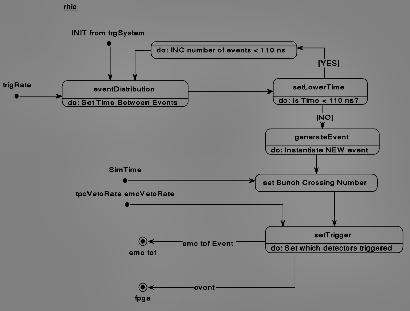
The bunch crossing number is set from the SimTime which is simulation time elapsed. The fundamental increment of time in the given simulation is 1 rhic strobe, but since this is a REAL, numbers < 1.0 are possible for time between events.
The tpcVetoRate and emcVetoRate are input variables which determine the rate of L0 triggered events. There are only 2 choices currently, TPC and EMC. For a TPC event all detectors (TPC, SVT, XTPC, EMC, TOF) are triggered, whereas an EMC event represents an interaction where only the EMC and TOF are triggered. Currently if there is a TPC triggered event but the TPC is busy the EMC/TOF trigger is set. This busy time with respect to triggered events is recorded, which of course represents detector deadtime.
Event objects with fields which describe the type of event, what detectors fired etc. are then moved to the emc/tof and fpga objects.
Back to the Object Model. J.P. Whitfield, Carnegie Mellon 4/20/95