STAR Offline QA Shift Histogram Description
This document lists the QA histograms for the Offline
QA Shifts for the Year 2001 data run. The present
set of plots are from the MDC4 year 2001 simulation
runs. In comparing the following page numbers and plots to
what you have in the actual QA postscript files for your specific
QA job you will notice that things do not match page-by-page.
The actual set of QA histograms generated during reconstruction
depends on the set of Makers which are active in the chain. However,
all plots in the EventQA_shiftLM, MM, and HM
files should be described here, just not in the same sequence.
A postscript version of the MDC4 QA Shift histograms
is available here.
Select the file EvQA_shift.ps.
Lanny Ray, The University of Texas at Austin
June 6, 2001
Page Index for QA Shift Plots
Page 1
Page 2
Page 3
Page 4
Page 5
Page 6
Page 7
Page 8
Page 9
Page 10
Page 11
Page 12
Page 13
Page 14
Page 15
Page 16
Page 17
Page 18
Page 19
Page 1
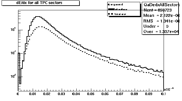 Distribution of truncated mean dE/dx for TPC outer (solid line)
and inner (dashed line) sectors. The outer sector values should
be larger than the inner sector due to the difference in
pad lengths. The distributions should have similar Landau
shapes. Peak position is nominally at ~0.015E-04 but could
vary depending on calibrations.
Distribution of truncated mean dE/dx for TPC outer (solid line)
and inner (dashed line) sectors. The outer sector values should
be larger than the inner sector due to the difference in
pad lengths. The distributions should have similar Landau
shapes. Peak position is nominally at ~0.015E-04 but could
vary depending on calibrations.
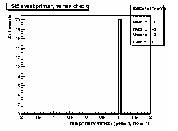 Primary vertex finding status for run; events with (1) and
without (-1) final vertex. The relative fraction of events
with primary vertex depends on trigger, beam diamond width
and position.
Primary vertex finding status for run; events with (1) and
without (-1) final vertex. The relative fraction of events
with primary vertex depends on trigger, beam diamond width
and position.
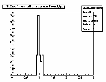 Ratio of total charge in all reconstructed clusters in TPC
east to west halves. Should be peaked at ~1 with FWHM ~ 0.5.
Ratio of total charge in all reconstructed clusters in TPC
east to west halves. Should be peaked at ~1 with FWHM ~ 0.5.
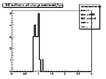 Ratio of total charge in all reconstructed clusters in FTPC
East to West. Should be peaked at ~1.
Ratio of total charge in all reconstructed clusters in FTPC
East to West. Should be peaked at ~1.
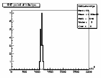 Distribution of number of reconstructed space points in TPC.
Should scale with centrality, depends on multiplicity cut
for this set of plots (i.e. low, medium or high).
Distribution of number of reconstructed space points in TPC.
Should scale with centrality, depends on multiplicity cut
for this set of plots (i.e. low, medium or high).
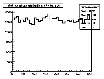
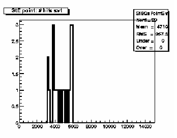 Distribution of number of reconstructed space points in SVT.
Should scale with centrality, depends on multiplicity cut
for this set of plots (i.e. low, medium or high). Also depends
strongly on vertex position distribution.
Distribution of number of reconstructed space points in SVT.
Should scale with centrality, depends on multiplicity cut
for this set of plots (i.e. low, medium or high). Also depends
strongly on vertex position distribution.
Page 2
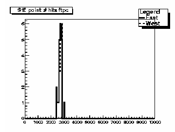 Distribution of number of reconstructed space points in
FTPC East (solid line) and West (dashed line). Should have
similar means and widths; scales with centrality,
depends on multiplicity cut for this set of plots
(i.e. low, medium or high).
Distribution of number of reconstructed space points in
FTPC East (solid line) and West (dashed line). Should have
similar means and widths; scales with centrality,
depends on multiplicity cut for this set of plots
(i.e. low, medium or high).
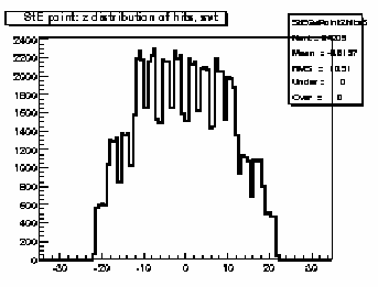
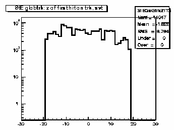
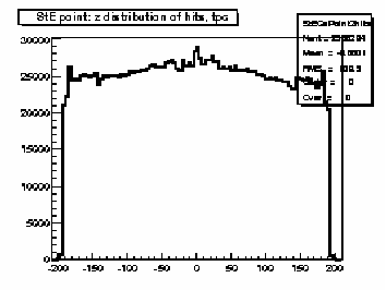 Distribution of reconstructed space points in TPC with
respect to z-coordinate. Should be flat within statistics. Watch out
for anamolous peaks at z=0 (central membrane), steps
or unusual spikes or dips. Some roll-off at the ends
is normal.
Distribution of reconstructed space points in TPC with
respect to z-coordinate. Should be flat within statistics. Watch out
for anamolous peaks at z=0 (central membrane), steps
or unusual spikes or dips. Some roll-off at the ends
is normal.
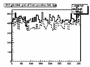
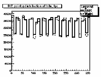 Distribution of reconstructed space points in TPC with
respect to azimuthal coordinate (phi) for east (solid line)
and west (dashed line) halves. Should be flat
except for the 12-fold sector structure.
Distribution of reconstructed space points in TPC with
respect to azimuthal coordinate (phi) for east (solid line)
and west (dashed line) halves. Should be flat
except for the 12-fold sector structure.
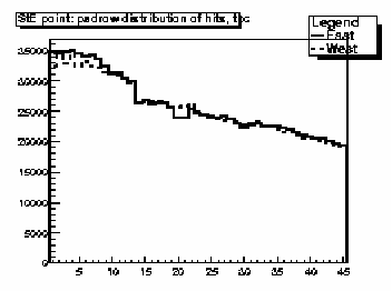 Distribution of reconstructed space points in TPC with
respect to padrow number 1-45. Should display gradual
fall-off; watch for anamolous spikes and dips.
Distribution of reconstructed space points in TPC with
respect to padrow number 1-45. Should display gradual
fall-off; watch for anamolous spikes and dips.
 Distribution of reconstructed space points in SVT with
respect to z-coordinate. Should be flat within statistics with step like
drop off at larger abs(z) due to SVT layers. Depends
on distribution of collision vertices.
Distribution of reconstructed space points in SVT with
respect to z-coordinate. Should be flat within statistics with step like
drop off at larger abs(z) due to SVT layers. Depends
on distribution of collision vertices.
 Distribution of reconstructed space points in SVT with
respect to azimuthal coordinate (phi). Should be flat
within statistics.
Distribution of reconstructed space points in SVT with
respect to azimuthal coordinate (phi). Should be flat
within statistics.
Page 3
 Distribution of reconstructed space points in SVT with
respect to layer number 1-3. Should have larger number
in outer 2 layers than the first.
Distribution of reconstructed space points in SVT with
respect to layer number 1-3. Should have larger number
in outer 2 layers than the first.
 Distribution of reconstructed space points assigned to
tracks in FTPC East (solid line) and West (dashed line) with respect
to padrow number. The horizontal axis shows padrow numbers
where FTPC-West is 1-10 and FTPC-East is 11-20. Pads
#1 and #11 are closest to the center of STAR. These should
be similar in shape and magnitude and should peak near the
middle of each detector.
Distribution of reconstructed space points assigned to
tracks in FTPC East (solid line) and West (dashed line) with respect
to padrow number. The horizontal axis shows padrow numbers
where FTPC-West is 1-10 and FTPC-East is 11-20. Pads
#1 and #11 are closest to the center of STAR. These should
be similar in shape and magnitude and should peak near the
middle of each detector.
 Distribution of hit multiplicity in the RICH detector.
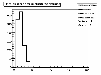
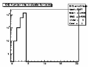 Distribution of number of hits per reconstructed energy
cluster in the EMC-barrel.
Distribution of number of hits per reconstructed energy
cluster in the EMC-barrel.
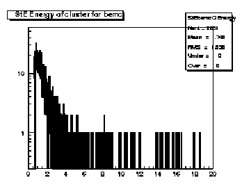 Distribution of energy in reconstructed clusters in EMC
barrel.
Distribution of energy in reconstructed clusters in EMC
barrel.
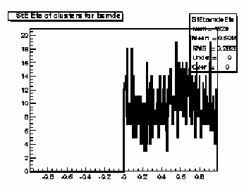
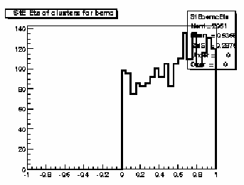 Pseudorapidity distribution of reconstructed energy
clusters in the EMC-barrel patch.
Pseudorapidity distribution of reconstructed energy
clusters in the EMC-barrel patch.
Page 4
 Azimuthal distribution of reconstructed energy
clusters in the EMC-barrel patch.
Azimuthal distribution of reconstructed energy
clusters in the EMC-barrel patch.
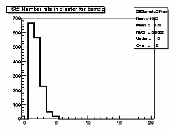
 Distribution of number of hits per reconstructed energy
cluster in the SMD pseudorapidity (eta) dependent wire patch.
Distribution of number of hits per reconstructed energy
cluster in the SMD pseudorapidity (eta) dependent wire patch.
 Pseudorapidity distribution of reconstructed energy
clusters in the SMD pseudorapidity (eta) dependent wire patch.
Pseudorapidity distribution of reconstructed energy
clusters in the SMD pseudorapidity (eta) dependent wire patch.
 Distribution of number of hits per reconstructed energy
cluster in the SMD azimuthal angle (phi) dependent wire patch.
Distribution of number of hits per reconstructed energy
cluster in the SMD azimuthal angle (phi) dependent wire patch.
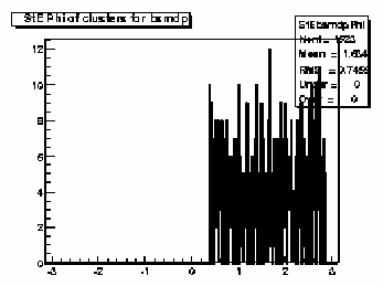 Azimuthal distribution of reconstructed energy
clusters in the SMD azimuthal angle (phi) dependent wire patch.
Azimuthal distribution of reconstructed energy
clusters in the SMD azimuthal angle (phi) dependent wire patch.
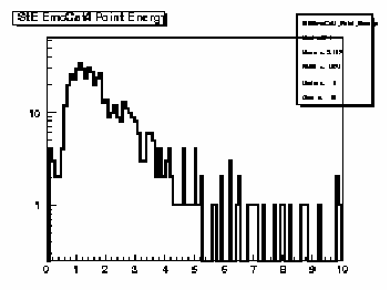 Energy distribution for EMC-SMD Category 4 clusters.
These correspond to matched clusters for the EMC barrel,
SMD-eta and SMD-phi.
Energy distribution for EMC-SMD Category 4 clusters.
These correspond to matched clusters for the EMC barrel,
SMD-eta and SMD-phi.
Page 5
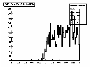 Pseudorapidity distribution of Category 4 EMC-SMD
clusters.
Pseudorapidity distribution of Category 4 EMC-SMD
clusters.
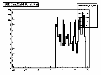 Azimuthal distribution (in radians) of Category 4 EMC-SMD
clusters.
Azimuthal distribution (in radians) of Category 4 EMC-SMD
clusters.
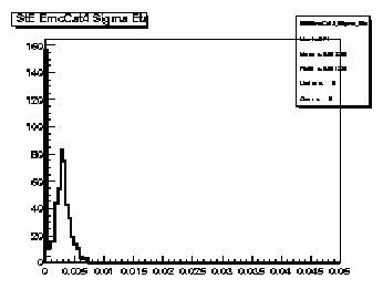 Distribution of widths (sigma) of Category 4 EMC-SMD
clusters with respect to pseudorapidity.
Distribution of widths (sigma) of Category 4 EMC-SMD
clusters with respect to pseudorapidity.
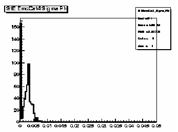 Distribution of widths (sigma) of Category 4 EMC-SMD
clusters with respect to azimuthal angle.
Distribution of widths (sigma) of Category 4 EMC-SMD
clusters with respect to azimuthal angle.
 Differences between centroids of Category 4 EMC-SMD
clusters and projected positions of TPC tracks at
EMC with respect to pseudorapidity. Should be peaked
at ~0.
Differences between centroids of Category 4 EMC-SMD
clusters and projected positions of TPC tracks at
EMC with respect to pseudorapidity. Should be peaked
at ~0.
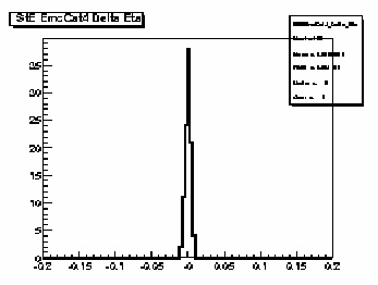
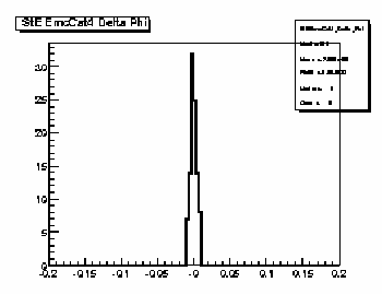 Differences between centroids of Category 4 EMC-SMD
clusters and projected positions of TPC tracks at
EMC with respect to azimuthal angle. Should be peaked
at ~0.
Differences between centroids of Category 4 EMC-SMD
clusters and projected positions of TPC tracks at
EMC with respect to azimuthal angle. Should be peaked
at ~0.
Page 6
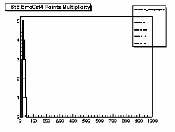 Multiplicity distribution of Category 4 EMC-SMD
clusters. Should scale with centrality, depends
on multiplicity cut for this set of plots
(i.e. low, medium or high).
Multiplicity distribution of Category 4 EMC-SMD
clusters. Should scale with centrality, depends
on multiplicity cut for this set of plots
(i.e. low, medium or high).
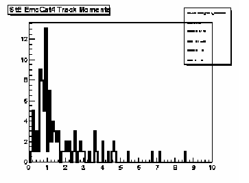 Distribution of momenta of global tracks matched to
Category 4 EMC-SMD clusters.
Distribution of momenta of global tracks matched to
Category 4 EMC-SMD clusters.
 Distribution of EMC and SMD cluster types by Category
number.
Distribution of EMC and SMD cluster types by Category
number.
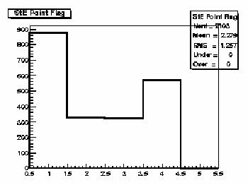
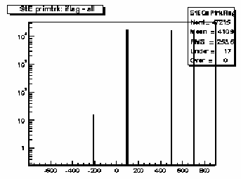
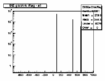 Quality flag values for all global tracks. Some with
large, negative values may not appear on plot; check
stat. box for underflows. Majority of tracks should
have iflag>0, corresponding to good, usable tracks.
Refer to:
dst_track_flags.html
and
kalerr.html
for description of flag values.
Quality flag values for all global tracks. Some with
large, negative values may not appear on plot; check
stat. box for underflows. Majority of tracks should
have iflag>0, corresponding to good, usable tracks.
Refer to:
dst_track_flags.html
and
kalerr.html
for description of flag values.
 Ratio of good global tracks to total for tracks
with TPC hits only, dashed line. Same for global
tracks with both SVT and TPC hits, solid line.
Both distributions should be a little less
than 1, with the SVT+TPC tracks being slightly
better.
Ratio of good global tracks to total for tracks
with TPC hits only, dashed line. Same for global
tracks with both SVT and TPC hits, solid line.
Both distributions should be a little less
than 1, with the SVT+TPC tracks being slightly
better.
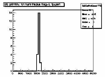
 Global track multiplicity distribution for TPC-only
and SVT+TPC tracks. Magnitude and width depends on
trigger condition and multiplicity cut for this
set of plots (i.e. low, medium or high).
Global track multiplicity distribution for TPC-only
and SVT+TPC tracks. Magnitude and width depends on
trigger condition and multiplicity cut for this
set of plots (i.e. low, medium or high).
Page 7
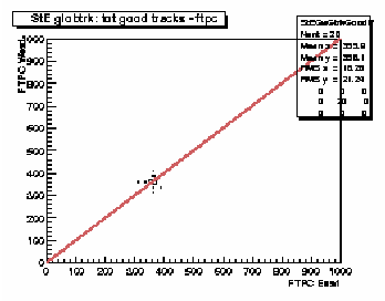 Scatter plot of good global track multiplicities in FTPC West
versus FTPC East. Distribution should be correlated and lie
along the reference diagonal line. Magnitudes and widths depend on
trigger condition and multiplicity cut for this
set of plots (i.e. low, medium or high).
Scatter plot of good global track multiplicities in FTPC West
versus FTPC East. Distribution should be correlated and lie
along the reference diagonal line. Magnitudes and widths depend on
trigger condition and multiplicity cut for this
set of plots (i.e. low, medium or high).
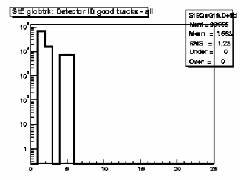 Global track detector IDs for good tracks. Refer to:
/afs/rhic/star/packages/DEV00/pams/global/inc/StDetectorDefinitions.h
for Detector ID codes.
Global track detector IDs for good tracks. Refer to:
/afs/rhic/star/packages/DEV00/pams/global/inc/StDetectorDefinitions.h
for Detector ID codes.
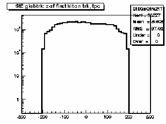
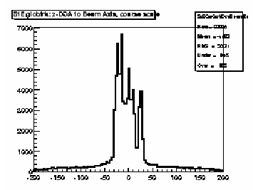 Coarse scale distribution along the z-axis (from -200 to +200 cm)
of the DCA points to the nominal beam line (z-axis, x=y=0)
for all TPC and SVT+TPC global tracks. Peaks indicate
probable locations of individual collision vertices.
There should be many peaks corresponding to the RHIC
beam-beam collision region.
Coarse scale distribution along the z-axis (from -200 to +200 cm)
of the DCA points to the nominal beam line (z-axis, x=y=0)
for all TPC and SVT+TPC global tracks. Peaks indicate
probable locations of individual collision vertices.
There should be many peaks corresponding to the RHIC
beam-beam collision region.
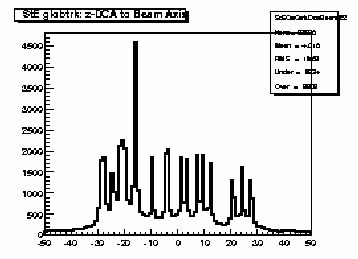 Fine scale distribution along the z-axis (from -50 to +50 cm)
of the DCA points to the nominal beam line (z-axis, x=y=0)
for all TPC and SVT+TPC global tracks. Peaks indicate
probable locations of individual collision vertices.
Peaks near the center should be narrower than those
beyond about 25 cm due to variations in the effective
radiation thickness of the SVT assembly along the z-axis.
Fine scale distribution along the z-axis (from -50 to +50 cm)
of the DCA points to the nominal beam line (z-axis, x=y=0)
for all TPC and SVT+TPC global tracks. Peaks indicate
probable locations of individual collision vertices.
Peaks near the center should be narrower than those
beyond about 25 cm due to variations in the effective
radiation thickness of the SVT assembly along the z-axis.
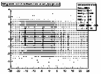 Scatter plot of the tangent of the dip angle (tanl) versus the
z-coordinate (from -25 to 25 cm) of the DCA points to the nominal beam line
(z-axis, x=y=0) for all TPC and SVT+TPC global tracks.
Vertical bands should be seen corresponding to individual
events. The bands should be smooth and continuous; breaks
at tanl=0 indicate probable TPC calibration errors in either the
t0 offset or the drift speed. This is best seen for
high multiplicity events.
Scatter plot of the tangent of the dip angle (tanl) versus the
z-coordinate (from -25 to 25 cm) of the DCA points to the nominal beam line
(z-axis, x=y=0) for all TPC and SVT+TPC global tracks.
Vertical bands should be seen corresponding to individual
events. The bands should be smooth and continuous; breaks
at tanl=0 indicate probable TPC calibration errors in either the
t0 offset or the drift speed. This is best seen for
high multiplicity events.
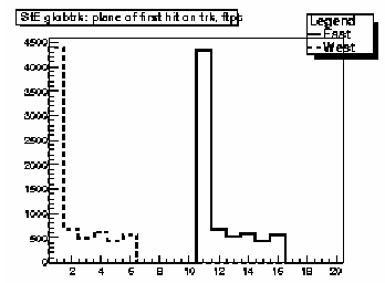
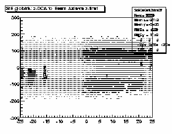 Scatter plot of the z-coordinate of the first fitted hit in the TPC
versus the z-coordinate (from -25 to 25 cm) of the DCA points
to the nominal beam line (z-axis, x=y=0) for all TPC-only global tracks
and SVT+TPC global tracks in which the
first point used in the fit lies in the TPC
(i.e. SVT assigned hits are thrown out during the fitting process).
Vertical bands should be seen corresponding to individual
events. The bands should be smooth and continuous; breaks
at z=0 indicate TPC calibration errors in either the
t0 offset or the drift speed. This is best seen for
high multiplicity events. This plot is of limited value compared to
the previous due to the SVT which catches most of the first hits.
Scatter plot of the z-coordinate of the first fitted hit in the TPC
versus the z-coordinate (from -25 to 25 cm) of the DCA points
to the nominal beam line (z-axis, x=y=0) for all TPC-only global tracks
and SVT+TPC global tracks in which the
first point used in the fit lies in the TPC
(i.e. SVT assigned hits are thrown out during the fitting process).
Vertical bands should be seen corresponding to individual
events. The bands should be smooth and continuous; breaks
at z=0 indicate TPC calibration errors in either the
t0 offset or the drift speed. This is best seen for
high multiplicity events. This plot is of limited value compared to
the previous due to the SVT which catches most of the first hits.
Page 8
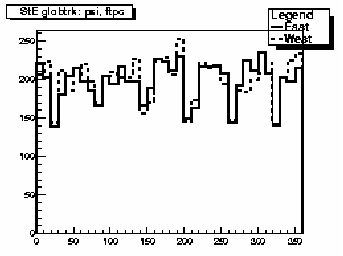
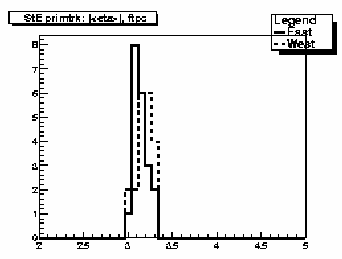
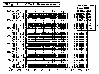 Scatter plot of the azimuthal direction angle (psi)
versus the z-coordinate (from -25 to 25 cm) of the DCA points
to the nominal beam line (z-axis, x=y=0) for all TPC and
SVT+TPC global tracks. Vertical bands should be seen
corresponding to individual events. The bands should be smooth,
straight and continuous indicating azimuthal symmetry in
the tracking. Bends or offsets could indicate problems in
individual TPC sectors such as voltage sags or drifts.
These are best studied with high multiplicity events.
Scatter plot of the azimuthal direction angle (psi)
versus the z-coordinate (from -25 to 25 cm) of the DCA points
to the nominal beam line (z-axis, x=y=0) for all TPC and
SVT+TPC global tracks. Vertical bands should be seen
corresponding to individual events. The bands should be smooth,
straight and continuous indicating azimuthal symmetry in
the tracking. Bends or offsets could indicate problems in
individual TPC sectors such as voltage sags or drifts.
These are best studied with high multiplicity events.
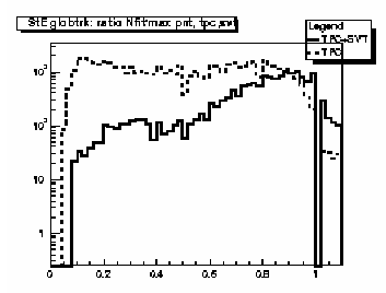
 Ratio of number of fitted points to total points on track
for TPC-only (dashed line) and SVT+TPC (solid line) global
tracks. Should peak at ~1.
Ratio of number of fitted points to total points on track
for TPC-only (dashed line) and SVT+TPC (solid line) global
tracks. Should peak at ~1.
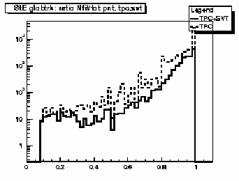
 Ratio of number of fitted points to estimated maximum
number for TPC-only (dashed line) and SVT+TPC (solid line) global
tracks. Peak at low value indicates track splitting.
Ratio for SVT+TPC global tracks should peak near 1.
Both distributions can extend above 1.
Ratio of number of fitted points to estimated maximum
number for TPC-only (dashed line) and SVT+TPC (solid line) global
tracks. Peak at low value indicates track splitting.
Ratio for SVT+TPC global tracks should peak near 1.
Both distributions can extend above 1.
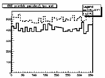
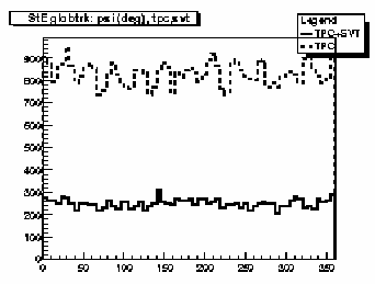 Azimuthal distributions for track direction angle (psi) for
TPC-only (dashed line) and SVT+TPC (solid line) global tracks.
Should be flat within statistics, except for the 12-sector
structure in the TPC-only global tracks.
Azimuthal distributions for track direction angle (psi) for
TPC-only (dashed line) and SVT+TPC (solid line) global tracks.
Should be flat within statistics, except for the 12-sector
structure in the TPC-only global tracks.
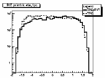
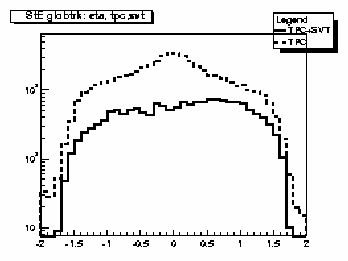 Pseudorapidity (eta) distributions for TPC-only (dashed line) and
SVT+TPC (solid line) global tracks. TPC track distribution should be symmetric
about eta=0. SVT+TPC track distribution may be non-symmetric depending on
the distribution of primary vertices.
Pseudorapidity (eta) distributions for TPC-only (dashed line) and
SVT+TPC (solid line) global tracks. TPC track distribution should be symmetric
about eta=0. SVT+TPC track distribution may be non-symmetric depending on
the distribution of primary vertices.
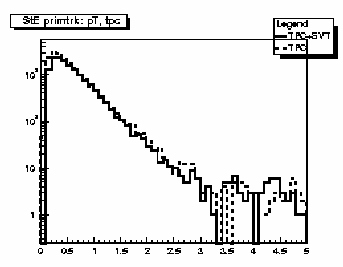
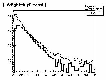 Transverse momentum (GeV/c) distributions for TPC-only
(dashed line) and SVT+TPC (solid line) global tracks.
Transverse momentum (GeV/c) distributions for TPC-only
(dashed line) and SVT+TPC (solid line) global tracks.
Page 9
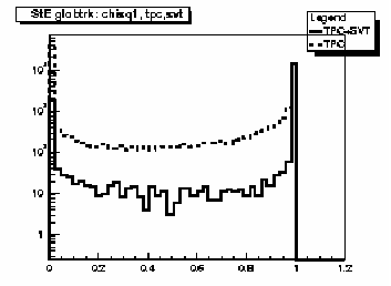
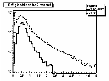 Chi-square per degree of freedom for TPC-only (dashed line)
and SVT+TPC (solid line) global tracks. Both should peak
just below 1.
Chi-square per degree of freedom for TPC-only (dashed line)
and SVT+TPC (solid line) global tracks. Both should peak
just below 1.
 Probability of chi-square for TPC-only (dashed line)
and SVT+TPC (solid line) global tracks. Both should
have strong peak at 1.
Probability of chi-square for TPC-only (dashed line)
and SVT+TPC (solid line) global tracks. Both should
have strong peak at 1.
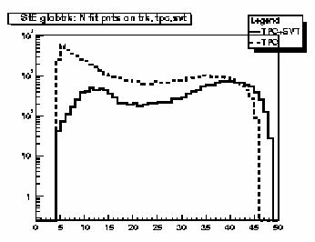 Distribution of the number of fitted points on track
for TPC-only (dashed line) and SVT+TPC (solid line)
global tracks. Peak at low value indicates track splitting.
Should see increase near ~45.
Distribution of the number of fitted points on track
for TPC-only (dashed line) and SVT+TPC (solid line)
global tracks. Peak at low value indicates track splitting.
Should see increase near ~45.
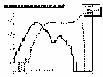 Log-base-10 of impact parameter (in cm) from primary vertex for
TPC-only (dashed line) and SVT+TPC (solid line) global tracks.
SVT+TPC tracks should have much smaller impact parameter values.
Log-base-10 of impact parameter (in cm) from primary vertex for
TPC-only (dashed line) and SVT+TPC (solid line) global tracks.
SVT+TPC tracks should have much smaller impact parameter values.
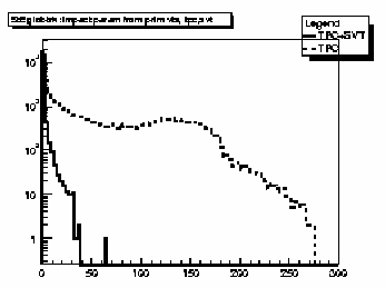 Impact parameter (in cm) from primary vertex for
TPC-only (dashed line) and SVT+TPC (solid line) global tracks.
SVT+TPC tracks should have much smaller impact parameter values.
Impact parameter (in cm) from primary vertex for
TPC-only (dashed line) and SVT+TPC (solid line) global tracks.
SVT+TPC tracks should have much smaller impact parameter values.
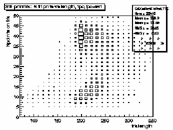
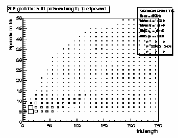 Scatter plot of number of fitted points on track versus track
length (from first to last point along helical path) for both
TPC-only and SVT+TPC global tracks. Peak in lower left corner
indicates split tracks. There should be some increase for >30
points and lengths from 1 - 2 m.
Scatter plot of number of fitted points on track versus track
length (from first to last point along helical path) for both
TPC-only and SVT+TPC global tracks. Peak in lower left corner
indicates split tracks. There should be some increase for >30
points and lengths from 1 - 2 m.
Page 10
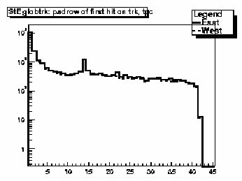 Distribution of first fitted space point with respect
to pad row number for TPC-only global tracks. Should
peak at 1 with a minor peak at padrow 14 (beginning of
outer sector); the latter should not be too
big relative to that at row 1.
Distribution of first fitted space point with respect
to pad row number for TPC-only global tracks. Should
peak at 1 with a minor peak at padrow 14 (beginning of
outer sector); the latter should not be too
big relative to that at row 1.
 Distribution of first fitted space point with respect
to z for TPC-only global tracks. Should be approx.
symmetric and flat around z=0.
Distribution of first fitted space point with respect
to z for TPC-only global tracks. Should be approx.
symmetric and flat around z=0.
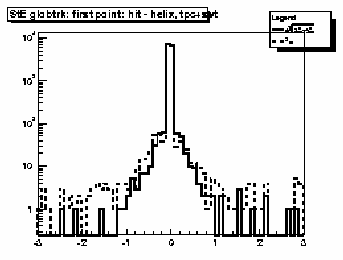
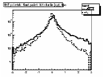
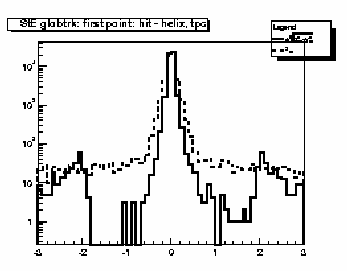 Residuals at first point on track for TPC-only global tracks.
The quantities plotted are the longitudinal (along z-axis, dashed line) and
transverse (in x-y plane, solid line) differences between the coordinates of
the first hit and the DCA point on the helix fit to the
first point. For the transverse residual, positive (negative)
values correspond to hits inside (outside) the
circular projection of the helix onto the bend plane. FWHM
should be less than ~ 1cm. The two bumps in the solid lines at +/- 2 cm
are due to an error in the QA_Maker software and should not appear in
the QA plots.
Residuals at first point on track for TPC-only global tracks.
The quantities plotted are the longitudinal (along z-axis, dashed line) and
transverse (in x-y plane, solid line) differences between the coordinates of
the first hit and the DCA point on the helix fit to the
first point. For the transverse residual, positive (negative)
values correspond to hits inside (outside) the
circular projection of the helix onto the bend plane. FWHM
should be less than ~ 1cm. The two bumps in the solid lines at +/- 2 cm
are due to an error in the QA_Maker software and should not appear in
the QA plots.
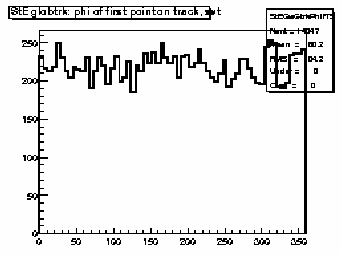
 Distribution of first fitted space point with respect
to azimuthal angle (phi) for TPC-only global tracks.
The solid (dashed) line is for the east (west) half of
the TPC. These should be approximately equal and flat
within statistics, except for the 12-sector structure.
Distribution of first fitted space point with respect
to azimuthal angle (phi) for TPC-only global tracks.
The solid (dashed) line is for the east (west) half of
the TPC. These should be approximately equal and flat
within statistics, except for the 12-sector structure.
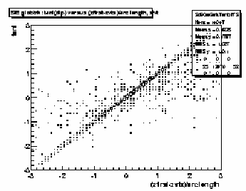
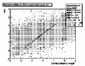 Scatter plot of tangent of dip angle (tanl) versus
(z_first - z_primvrtx)/arc-length for TPC-only global tracks
and SVT+TPC global tracks whose first fitted point is in
the TPC. Variable 'z_first' is the z coordinate of the first fitted
point in the TPC. Variable 'z_primvrtx' is the z-coordinate of the
primary vertex for the event. Variable 'arc-length' is 2R*arcsin(delta_r/2R)
where R = track radius of curvature and delta_r is the transverse
distance between the primary vertex and the first hit on track.
Primary tracks lie along the 45 deg diagonal. Secondary tracks
and strays lie scattered to either side. The diagonal band
should appear clearly and be straight and smooth without kinks,
breaks or bends.
Scatter plot of tangent of dip angle (tanl) versus
(z_first - z_primvrtx)/arc-length for TPC-only global tracks
and SVT+TPC global tracks whose first fitted point is in
the TPC. Variable 'z_first' is the z coordinate of the first fitted
point in the TPC. Variable 'z_primvrtx' is the z-coordinate of the
primary vertex for the event. Variable 'arc-length' is 2R*arcsin(delta_r/2R)
where R = track radius of curvature and delta_r is the transverse
distance between the primary vertex and the first hit on track.
Primary tracks lie along the 45 deg diagonal. Secondary tracks
and strays lie scattered to either side. The diagonal band
should appear clearly and be straight and smooth without kinks,
breaks or bends.
 Distribution of first fit hits with respect to z for
SVT+TPC global tracks which have the first fitted hit
in the SVT. Should be flat within statistics but could
display steps at the ends due to the SVT layers. Should
be approximately symmetric but depends on distribution of primary vertices.
Distribution of first fit hits with respect to z for
SVT+TPC global tracks which have the first fitted hit
in the SVT. Should be flat within statistics but could
display steps at the ends due to the SVT layers. Should
be approximately symmetric but depends on distribution of primary vertices.
Page 11
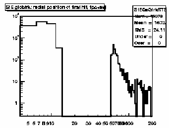 Distribution of radial position of first fitted hits
on SVT+TPC global tracks. Tracks on the right side
correspond to those in which the SVT space points were
discarded by the fitter.
Distribution of radial position of first fitted hits
on SVT+TPC global tracks. Tracks on the right side
correspond to those in which the SVT space points were
discarded by the fitter.
 Residuals at first point on track for SVT+TPC global tracks.
The quantities plotted are the longitudinal (along z-axis, dashed line) and
transverse (in x-y plane, solid line) differences between the coordinates of
the first hit and the DCA point on the helix fit to the
first point. For the transverse residual, positive (negative)
values correspond to hits inside (outside) the
circular projection of the helix onto the bend plane. FWHM
should be less than ~ 0.1 cm. Broad, ~1 cm wide tails,
could be due to tracks in which the SVT hits were discarded by the fitter.
Residuals at first point on track for SVT+TPC global tracks.
The quantities plotted are the longitudinal (along z-axis, dashed line) and
transverse (in x-y plane, solid line) differences between the coordinates of
the first hit and the DCA point on the helix fit to the
first point. For the transverse residual, positive (negative)
values correspond to hits inside (outside) the
circular projection of the helix onto the bend plane. FWHM
should be less than ~ 0.1 cm. Broad, ~1 cm wide tails,
could be due to tracks in which the SVT hits were discarded by the fitter.
 Distribution of first fitted space point with respect
to azimuthal angle (phi) for SVT+TPC global tracks with
first point in the SVT.
These should be approximately equal and flat
within statistics.
Distribution of first fitted space point with respect
to azimuthal angle (phi) for SVT+TPC global tracks with
first point in the SVT.
These should be approximately equal and flat
within statistics.
 Scatter plot of tangent of dip angle (tanl) versus
(z_first - z_primvrtx)/arc-length for SVT+TPC global tracks
with first point in the SVT.
Variable 'z_first' is the z coordinate of the first fitted
point in the SVT. Variable 'z_primvrtx' is the z-coordinate of the
primary vertex for the event. Variable 'arc-length' is 2R*arcsin(delta_r/2R)
where R = track radius of curvature and delta_r is the transverse
distance between the primary vertex and the first hit on track.
Primary tracks lie along the 45 deg diagonal. Secondary tracks
and strays lie scattered to either side. The diagonal band
should appear clearly and be straight and smooth without kinks, breaks
or bends. This should be much cleaner than that for the TPC-only
tracks.
Scatter plot of tangent of dip angle (tanl) versus
(z_first - z_primvrtx)/arc-length for SVT+TPC global tracks
with first point in the SVT.
Variable 'z_first' is the z coordinate of the first fitted
point in the SVT. Variable 'z_primvrtx' is the z-coordinate of the
primary vertex for the event. Variable 'arc-length' is 2R*arcsin(delta_r/2R)
where R = track radius of curvature and delta_r is the transverse
distance between the primary vertex and the first hit on track.
Primary tracks lie along the 45 deg diagonal. Secondary tracks
and strays lie scattered to either side. The diagonal band
should appear clearly and be straight and smooth without kinks, breaks
or bends. This should be much cleaner than that for the TPC-only
tracks.
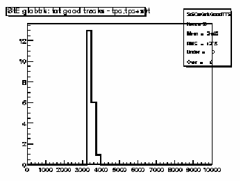
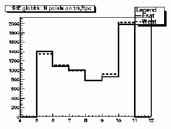 Distribution of the number of fitted points on track
for FTPC-East (solid line) and FTPC-West (dashed line)
global tracks. Distributions should be similar within
statistics and peak at 10.
Distribution of the number of fitted points on track
for FTPC-East (solid line) and FTPC-West (dashed line)
global tracks. Distributions should be similar within
statistics and peak at 10.
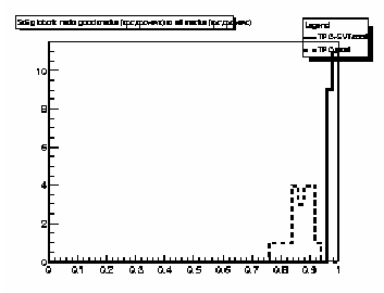
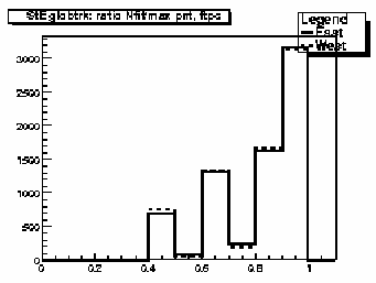 Ratio of number of fitted points to estimated maximum
number for FTPC-East (solid line) and FTPC-West (dashed line) global
tracks. Should peak at ~1. Distributions should be
similar within statistics.
Ratio of number of fitted points to estimated maximum
number for FTPC-East (solid line) and FTPC-West (dashed line) global
tracks. Should peak at ~1. Distributions should be
similar within statistics.
Page 12
 Distribution of first fitted space point with respect to
FTPC pad row number (West is 1-10, dashed line; East is
11-20, solid line) for FTPC global tracks.
These should be similar within statistics
and peak at pad rows 1 and 11.
Distribution of first fitted space point with respect to
FTPC pad row number (West is 1-10, dashed line; East is
11-20, solid line) for FTPC global tracks.
These should be similar within statistics
and peak at pad rows 1 and 11.
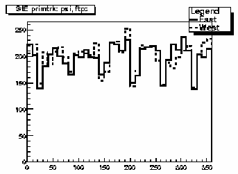
 Azimuthal distributions for track direction angle (psi) for
FTPC-East (solid line) and FTPC-West (dashed line) global tracks.
These should be similar and flat within statistics except for
the hexagonal FTPC sector structure.
Azimuthal distributions for track direction angle (psi) for
FTPC-East (solid line) and FTPC-West (dashed line) global tracks.
These should be similar and flat within statistics except for
the hexagonal FTPC sector structure.
 Distributions of absolute value of pseudorapidity for
FTPC-East (solid line) and FTPC-West (dashed line) global tracks.
These should be similar within statistics and range from about
2.5 to 4.
Distributions of absolute value of pseudorapidity for
FTPC-East (solid line) and FTPC-West (dashed line) global tracks.
These should be similar within statistics and range from about
2.5 to 4.
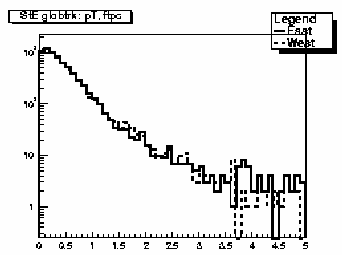 Transverse momentum (GeV/c) distributions for
FTPC-East (solid line) and FTPC-West (dashed line) global tracks.
These should be similar within statistics.
Transverse momentum (GeV/c) distributions for
FTPC-East (solid line) and FTPC-West (dashed line) global tracks.
These should be similar within statistics.
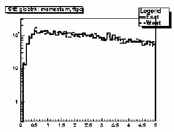 Total momentum (GeV/c) distributions for
FTPC-East (solid line) and FTPC-West (dashed line) global tracks.
These should be similar within statistics.
Total momentum (GeV/c) distributions for
FTPC-East (solid line) and FTPC-West (dashed line) global tracks.
These should be similar within statistics.
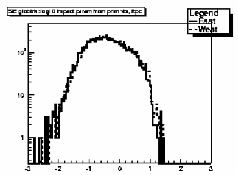 Log-base-10 of impact parameter (in cm) from primary vertex for
FTPC-East (solid line) and FTPC-West (dashed line) global tracks.
These should be similar within statistics.
Log-base-10 of impact parameter (in cm) from primary vertex for
FTPC-East (solid line) and FTPC-West (dashed line) global tracks.
These should be similar within statistics.
Page 13
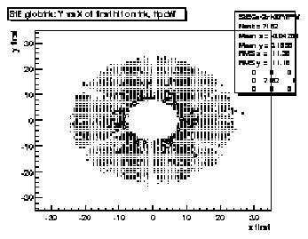
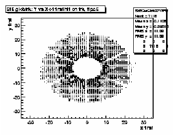 Scatter plot of (x,y) coordinates for the first fitted
space points in FTPC-East global tracks.
These should be uniformly populated
with hits; FTPC hexagonal structure is apparent.
Scatter plot of (x,y) coordinates for the first fitted
space points in FTPC-East global tracks.
These should be uniformly populated
with hits; FTPC hexagonal structure is apparent.
 Scatter plot of (x,y) coordinates for the first fitted
space points in FTPC-West global tracks.
These should be uniformly populated
with hits; FTPC hexagonal structure is apparent.
Scatter plot of (x,y) coordinates for the first fitted
space points in FTPC-West global tracks.
These should be uniformly populated
with hits; FTPC hexagonal structure is apparent.
 Quality flag values for all primary tracks. Some with
large, negative values may not appear on plot; check
stat. box for underflows. Majority of tracks should
have iflag>0, corresponding to good, usable tracks.
Refer to:
dst_track_flags.html
and
kalerr.html
for description of flag values.
Quality flag values for all primary tracks. Some with
large, negative values may not appear on plot; check
stat. box for underflows. Majority of tracks should
have iflag>0, corresponding to good, usable tracks.
Refer to:
dst_track_flags.html
and
kalerr.html
for description of flag values.
 Good primary track multiplicity distribution for TPC-only
and SVT+TPC tracks. Magnitude and width depends on
trigger condition and multiplicity cut for this
set of plots (i.e. low, medium or high).
Good primary track multiplicity distribution for TPC-only
and SVT+TPC tracks. Magnitude and width depends on
trigger condition and multiplicity cut for this
set of plots (i.e. low, medium or high).
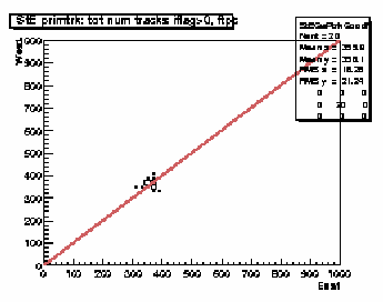 Scatter plot of good primary track multiplicities in FTPC West
versus FTPC East. Distribution should be correlated and lie
along the reference diagonal line. Magnitudes and widths depend on
trigger condition and multiplicity cut for this
set of plots (i.e. low, medium or high).
Scatter plot of good primary track multiplicities in FTPC West
versus FTPC East. Distribution should be correlated and lie
along the reference diagonal line. Magnitudes and widths depend on
trigger condition and multiplicity cut for this
set of plots (i.e. low, medium or high).
 Ratio of good primary to good global tracks for all detectors. Should
be of order 1/3 to 2/3.
Ratio of good primary to good global tracks for all detectors. Should
be of order 1/3 to 2/3.
Page 14
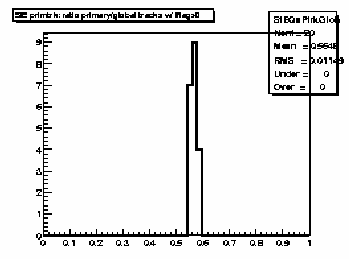
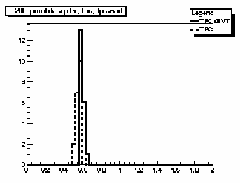 Mean transverse momentum distribution for TPC-only (dashed line)
and SVT+TPC (solid line) good primary tracks. Should peak around
0.4 - 0.6 GeV/c and be fairly narrow.
Mean transverse momentum distribution for TPC-only (dashed line)
and SVT+TPC (solid line) good primary tracks. Should peak around
0.4 - 0.6 GeV/c and be fairly narrow.
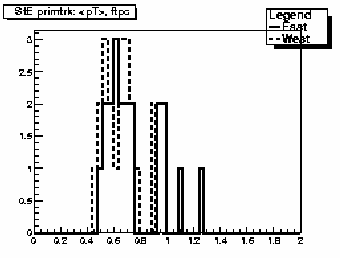 Mean transverse momentum distribution for FTPC-East (solid line)
and FTPC-West (dashed line) good primary tracks. These should be
similar within statistics and peak around 0.4 - 0.6 GeV/c but can
have broader distributions than for the SVT and TPC tracks.
Mean transverse momentum distribution for FTPC-East (solid line)
and FTPC-West (dashed line) good primary tracks. These should be
similar within statistics and peak around 0.4 - 0.6 GeV/c but can
have broader distributions than for the SVT and TPC tracks.
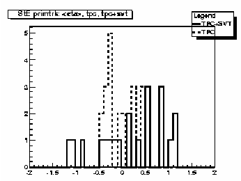 Mean pseudorapidity distribution for TPC-only (dashed line)
and SVT+TPC (solid line) good primary tracks. Should peak around
0 but can be fairly broad depending on distribution of primary vertices.
Mean pseudorapidity distribution for TPC-only (dashed line)
and SVT+TPC (solid line) good primary tracks. Should peak around
0 but can be fairly broad depending on distribution of primary vertices.
 Distribution of absolute value of mean pseudorapidity for FTPC-East
(solid line) and FTPC-West (dashed line) good primary tracks.
These should be similar within statistics and peak
around 3 - 3.5.
Distribution of absolute value of mean pseudorapidity for FTPC-East
(solid line) and FTPC-West (dashed line) good primary tracks.
These should be similar within statistics and peak
around 3 - 3.5.
 Azimuthal distributions for track direction angle (psi) for
TPC-only (dashed line) and SVT+TPC (solid line) good primary tracks.
Should be flat within statistics.
Azimuthal distributions for track direction angle (psi) for
TPC-only (dashed line) and SVT+TPC (solid line) good primary tracks.
Should be flat within statistics.
 Pseudorapidity (eta) distributions for TPC-only (dashed line) and
SVT+TPC (solid line) primary tracks. TPC tracks should be symmetric
about eta=0. SVT+TPC may have slight non-symmetry depending on
distribution of primary vertices.
Pseudorapidity (eta) distributions for TPC-only (dashed line) and
SVT+TPC (solid line) primary tracks. TPC tracks should be symmetric
about eta=0. SVT+TPC may have slight non-symmetry depending on
distribution of primary vertices.
Page 15
 Transverse momentum (GeV/c) distributions for TPC-only
(dashed line) and SVT+TPC (solid line) primary tracks.
Transverse momentum (GeV/c) distributions for TPC-only
(dashed line) and SVT+TPC (solid line) primary tracks.
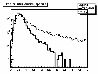 Chi-square per degree of freedom for TPC-only (dashed line)
and SVT+TPC (solid line) primary tracks. Both should peak
just below 1.
Chi-square per degree of freedom for TPC-only (dashed line)
and SVT+TPC (solid line) primary tracks. Both should peak
just below 1.
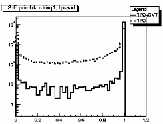 Probability of chi-square for TPC-only (dashed line)
and SVT+TPC (solid line) primary tracks. Both should
have strong peak at 1.
Probability of chi-square for TPC-only (dashed line)
and SVT+TPC (solid line) primary tracks. Both should
have strong peak at 1.
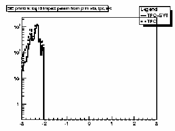 Log-base-10 of impact parameter (in cm) from primary vertex for
TPC-only (dashed line) and SVT+TPC (solid line) primary tracks.
If the primary track refit is constrained to go through the
primary vertex then the impact parameter will be very small.
Log-base-10 of impact parameter (in cm) from primary vertex for
TPC-only (dashed line) and SVT+TPC (solid line) primary tracks.
If the primary track refit is constrained to go through the
primary vertex then the impact parameter will be very small.
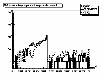 Impact parameter (in cm) from primary vertex for
TPC-only (dashed line) and SVT+TPC (solid line) primary tracks.
If the primary track refit is constrained to go through the
primary vertex then the impact parameter will be very small.
Impact parameter (in cm) from primary vertex for
TPC-only (dashed line) and SVT+TPC (solid line) primary tracks.
If the primary track refit is constrained to go through the
primary vertex then the impact parameter will be very small.
 Scatter plot of number of fitted points on track versus track
length (from first to last point along helical path) for both
TPC-only and SVT+TPC primary tracks. There should not be a
peak in lower left corner
indicating fewer split tracks than for global tracks.
There should be a peak(s) for long tracks above 1.5 m.
Scatter plot of number of fitted points on track versus track
length (from first to last point along helical path) for both
TPC-only and SVT+TPC primary tracks. There should not be a
peak in lower left corner
indicating fewer split tracks than for global tracks.
There should be a peak(s) for long tracks above 1.5 m.
Page 16
 Residuals at first point on track for TPC-only primary tracks.
The quantities plotted are the longitudinal (along z-axis, dashed line) and
transverse (in x-y plane, solid line) differences between the coordinates of
the first hit and the DCA point on the helix fit to the
first point. For the transverse residual, positive (negative)
values correspond to hits inside (outside) the
circular projection of the helix onto the bend plane. FWHM
should be less than ~ 1cm.
Residuals at first point on track for TPC-only primary tracks.
The quantities plotted are the longitudinal (along z-axis, dashed line) and
transverse (in x-y plane, solid line) differences between the coordinates of
the first hit and the DCA point on the helix fit to the
first point. For the transverse residual, positive (negative)
values correspond to hits inside (outside) the
circular projection of the helix onto the bend plane. FWHM
should be less than ~ 1cm.
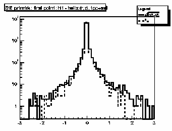 Residuals at first point on track for SVT+TPC primary tracks.
The quantities plotted are the longitudinal (along z-axis, dashed line) and
transverse (in x-y plane, solid line) differences between the coordinates of
the first hit and the DCA point on the helix fit to the
first point. For the transverse residual, positive (negative)
values correspond to hits inside (outside) the
circular projection of the helix onto the bend plane. FWHM
should be less than ~ 0.1 cm. Broad, ~1 cm wide tails
could be due to tracks in which the SVT hits were discarded by the fitter.
Residuals at first point on track for SVT+TPC primary tracks.
The quantities plotted are the longitudinal (along z-axis, dashed line) and
transverse (in x-y plane, solid line) differences between the coordinates of
the first hit and the DCA point on the helix fit to the
first point. For the transverse residual, positive (negative)
values correspond to hits inside (outside) the
circular projection of the helix onto the bend plane. FWHM
should be less than ~ 0.1 cm. Broad, ~1 cm wide tails
could be due to tracks in which the SVT hits were discarded by the fitter.
 Azimuthal distributions for track direction angle (psi) for
FTPC-East (solid line) and FTPC-West (dashed line) primary tracks.
These should be similar and flat within statistics except for
the hexagonal FTPC sector structure.
Azimuthal distributions for track direction angle (psi) for
FTPC-East (solid line) and FTPC-West (dashed line) primary tracks.
These should be similar and flat within statistics except for
the hexagonal FTPC sector structure.
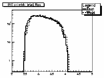 Distributions of absolute value of pseudorapidity for
FTPC-East (solid line) and FTPC-West (dashed line) primary tracks.
These should be similar within statistics and range from about
2.5 to 4.
Distributions of absolute value of pseudorapidity for
FTPC-East (solid line) and FTPC-West (dashed line) primary tracks.
These should be similar within statistics and range from about
2.5 to 4.
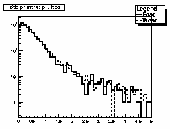 Transverse momentum (GeV/c) distributions for
FTPC-East (solid line) and FTPC-West (dashed line) primary tracks.
These should be similar within statistics.
Transverse momentum (GeV/c) distributions for
FTPC-East (solid line) and FTPC-West (dashed line) primary tracks.
These should be similar within statistics.
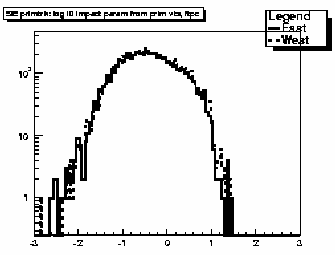 Log-base-10 of impact parameter (in cm) from primary vertex for
FTPC-East (solid line) and FTPC-West (dashed line) primary tracks.
These should be similar within statistics.
Log-base-10 of impact parameter (in cm) from primary vertex for
FTPC-East (solid line) and FTPC-West (dashed line) primary tracks.
These should be similar within statistics.
Page 17
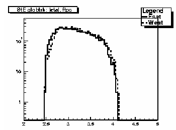
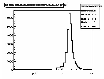 Distribution of ratio of mean dE/dx to Bethe-Bloch dE/dx for pions at the same
momentum for TPC-only and SVT+TPC global tracks. Should peak at ~1.
Tests calibration of charge deposition in TPC gas.
Distribution of ratio of mean dE/dx to Bethe-Bloch dE/dx for pions at the same
momentum for TPC-only and SVT+TPC global tracks. Should peak at ~1.
Tests calibration of charge deposition in TPC gas.
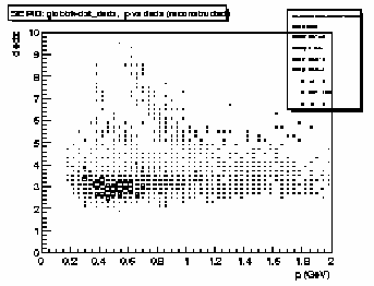 Scatter plot of truncated mean dE/dx versus total momentum (GeV/c)
for TPC-only and SVT+TPC global tracks. Should be able to see
Bethe-Bloch bands for pions, kaons and protons.
Scatter plot of truncated mean dE/dx versus total momentum (GeV/c)
for TPC-only and SVT+TPC global tracks. Should be able to see
Bethe-Bloch bands for pions, kaons and protons.
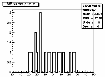 Distribution of primary vertex position along the z-axis out to
abs(z) < 50 cm. This should correspond to the RHIC bunch length,
crossing and cogging information.
Distribution of primary vertex position along the z-axis out to
abs(z) < 50 cm. This should correspond to the RHIC bunch length,
crossing and cogging information.
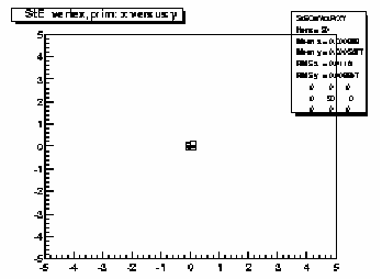 Scatter plot of the (x,y) coordinates of the primary vertex
position. This should correspond to the determined beam
transverse position. The amount of dispersion will depend
on the trigger condition and multiplicity cut for this
set of plots (i.e. low, medium or high).
Scatter plot of the (x,y) coordinates of the primary vertex
position. This should correspond to the determined beam
transverse position. The amount of dispersion will depend
on the trigger condition and multiplicity cut for this
set of plots (i.e. low, medium or high).
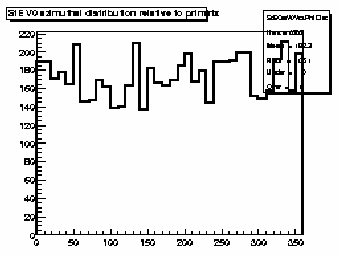 Azimuthal distribution of V0 vertices relative to the primary
vertex for each event. Should be flat within statistics.
Azimuthal distribution of V0 vertices relative to the primary
vertex for each event. Should be flat within statistics.
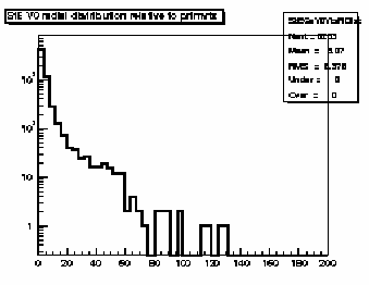 Radial distribution of V0 vertices relative to the primary
vertex for each event. Should fall off steeply with most
vertices within ~10 cm.
Radial distribution of V0 vertices relative to the primary
vertex for each event. Should fall off steeply with most
vertices within ~10 cm.
Page 18
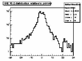 Longitudinal (z) distribution of V0 vertices relative to the primary
vertex for each event. Should fall off steeply with most
vertices within ~10 cm.
Longitudinal (z) distribution of V0 vertices relative to the primary
vertex for each event. Should fall off steeply with most
vertices within ~10 cm.
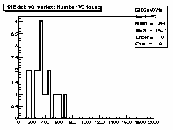 Total number of V0 vertices found in each event; should scale
with multiplicity. Range depends on trigger condition
and multiplicity cut for this
set of plots (i.e. low, medium or high).
Total number of V0 vertices found in each event; should scale
with multiplicity. Range depends on trigger condition
and multiplicity cut for this
set of plots (i.e. low, medium or high).
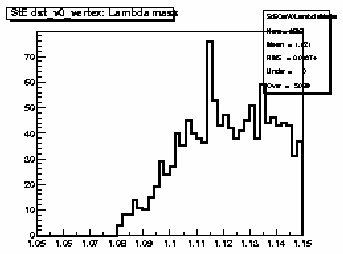 Invariant mass plot of V0 vertices using Lambda decay hypothesis.
Sometimes possible to see Lambda peak for low- and
mid-multiplicity events.
Invariant mass plot of V0 vertices using Lambda decay hypothesis.
Sometimes possible to see Lambda peak for low- and
mid-multiplicity events.
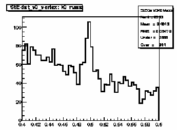 Invariant mass plot of V0 vertices using K0-short decay hypothesis.
Sometimes possible to see K0-short peak for low- and
mid-multiplicity events.
Invariant mass plot of V0 vertices using K0-short decay hypothesis.
Sometimes possible to see K0-short peak for low- and
mid-multiplicity events.
 Total number of Xi vertices found in each event; should scale
with multiplicity. Range depends on trigger condition
and multiplicity cut for this
set of plots (i.e. low, medium or high).
Total number of Xi vertices found in each event; should scale
with multiplicity. Range depends on trigger condition
and multiplicity cut for this
set of plots (i.e. low, medium or high).
 Total number of kink decay vertices found in each event; should scale
with multiplicity. Range depends on trigger condition
and multiplicity cut for this
set of plots (i.e. low, medium or high).
Total number of kink decay vertices found in each event; should scale
with multiplicity. Range depends on trigger condition
and multiplicity cut for this
set of plots (i.e. low, medium or high).
Page 19
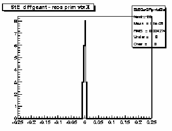 Difference between the geant and reconstructed primary vertex
position along coordinate x (cm). For simulations only.
Difference between the geant and reconstructed primary vertex
position along coordinate x (cm). For simulations only.
 Difference between the geant and reconstructed primary vertex
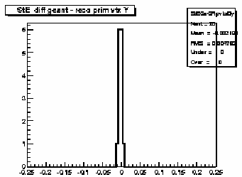
position along coordinate y (cm). For simulations only.
Difference between the geant and reconstructed primary vertex
position along coordinate y (cm). For simulations only.
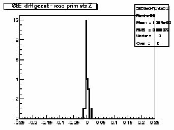 Difference between the geant and reconstructed primary vertex
position along coordinate z (cm). For simulations only.
Difference between the geant and reconstructed primary vertex
position along coordinate z (cm). For simulations only.