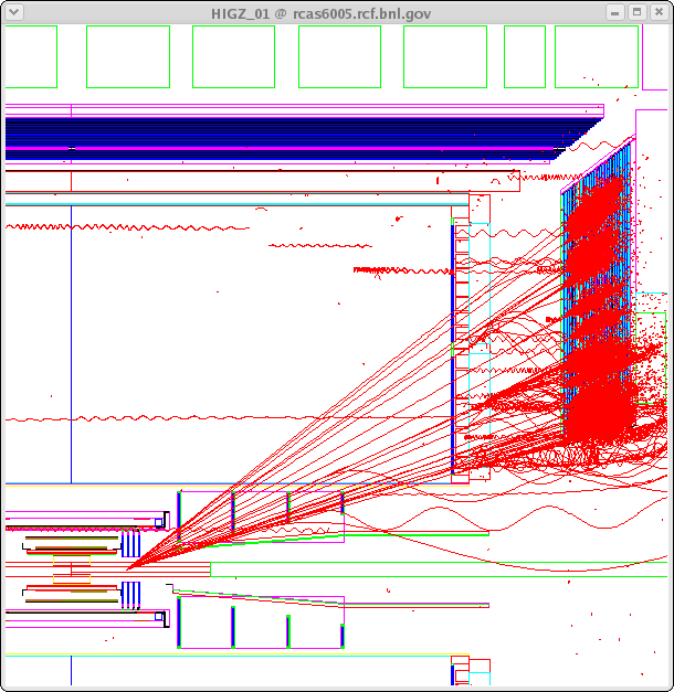
Generated electrons have fixed pT and zVertex of -30, 0, or +30 cm, and uniform eta and phi distribution. Sample of high pT electrons thrown from different zVertex location over eta range [1,2] are shown here: Z=-30cm , Z=0cm , Z=+30cm, or combined 3Z locations.
The plot shows 9 electrons with fixed pT=40 GeV/c, Z={-30,0,+30}cm, and eta={1.0,1.5,2.0}

* Use: Vertex, IST1+2, SSD, new FGT, truncated TPC(nHit>=5), ESMD (also try FST)
| detector | assumed resolution | weight of the point | Remarks |
|---|---|---|---|
| vertex | 200 mu m in X,Y,Z | W=1/(200 mu m)^2 | added as a hit |
| IST1 | 20 mum in r*phi 0.5 mm in Z | W=1/(20 mu m)^2 | - |
| IST2 | 0.5 mm in r*phi 20 mum in Z | W=1/(0.5 mm)^2 | - |
| SSD | 20 mum in r*phi 1 mm in Z | W=1/(20 mu m)^2 | - |
| (FST) | 20 or 60 mu m in X,Y 10 mu in Z | W=1/(20 or 60 mu m)^2 | 2 disks: 1st & 4th, used only in config B & C |
| FGT mock hit | 60 mu m in X,Y 10 mu in Z | W=1/(60 mu m)^2 | 6 disks *), see plot , config=D uses 4 disks |
| TPC | 1 mm along arc 1 mm in Z | W=1/(1mm)^2 | * drop padrow #1 and #13 * drop hits at |Z|>197 cm * drop all hits if below 5 |
| Endcap SMD
mock hit **) | 1.5 mm in X,Y,Z | W=1/(1.5 mm)^2 | at xPoint of Geant helix w/ SMD plane |
(i) 6 disks: zStep=18 cm, Rin(z)/cm=3+ (z-60)/4, Rout=43cm=const
(ii) 4 disks: zStep=30 cm, Rin(z)/cm=3+ (z-60)/4, Rout=43cm=const
**) Based on SMD response study by Jim
Z vertex= - 30 cm 
| Z vertex= 0 cm 
| Z vertex= + 30 cm 
|
|---|
| Config | FST | FGT ( 60 mum ) | Vertex,IST,SSD,TPC,ESMD |
|---|---|---|---|
| A | no | 6 disks | all ON = default |
| B | 2 disks, 60 mum | 6 disks | all ON |
| C | 2 disks, 20 mum | 6 disks | all ON |
| D | no | 4 disks over the same z-range | all ON |
| E | no | no | all ON |
| E1 | no | no | ESMD sigX,Y=15 cm |
More configurations requested by Bernd, Will --> plots are here.
| Config | FST | FGT 6 disks |
|---|---|---|
| A1 | no | degrade to 80 mum |
| A2 | no | degrade to100 mum |
| A3 | no | degrade to 120 mum |
| A4 | no | degrade vertex sigX,Y,Z from 0.2 --> 0.5mm |
| A5 | no | degrade vertex sigX,Y,Z from 0.2 --> 1.0mm |
| A6 | no | degrade only vertex sigZ from 0.2 --> 30 cm, assume only beamLin constrian is used. BBC could give us 30 cm vertex-Z resolution. |
| A7 | no | degrade FGT disk efficinfy to 90% |
| A8 | no | degrade FGT disk efficinfy to 85% |
Track reco efficiency is defined as the ratio of# of reco tracks (N1) w/
* nFitP>=5, including vertex as a hit
* delPhi<3 mrad
* delTheta <3 mrad
to the # of generated electrons (N0).
Charge reco efficiency requiers additinal
* the sign of the reco charge is correct. Track counter is N2.
No cut on reco pT is imposed.
Note, we do not want to be in the magenta sqare.
| track Eff= N1/N0 | charg eff = N2/N0 | wrong charge (N1-N2)/N1 |
|---|---|---|
| Config A : 6 FGT disks, no FST | ||

| 
| 
|
| - | ||
| Config B : 6 FGT disks + 2 FST disks (60 mum) | ||

| 
| 
|
| - | ||
| Config C : 6 FGT disks + 2 FST disks (20 mum) | ||

| 
| 
|
| - | ||
| Config D : 4 FGT disks over same z range, no FST | ||

| 
| 
|
| - | ||
| Config E : no FST, no FGT | ||

| 
| 
|
| - | ||
| Config E1 : no FST, no FGT, ESMDsig=15cm | ||

| 
| 
|
- 6 FGT disks provides charge reco efficiency above 80% and contamination below 20% for eta<2.0 and zVertex in [-30,+30]cm.
- FGT Rout=43 cm is perhaps to high, repositioning of the disk #4 to a smaller Z will allow to reduce its Rout (I hope).
- FST does not improve charge reco efficiency since it always overlaps with many FGT or TPC layers.
- 4 FGT disks reduces charge reco for eta>1.5
PR plots:
* comparison of charge efficiency for proposed configuration A, vs. if FGT is dropped (Conf=E), vs. if also ESMD point is degraded (conf=E1), PS version

* Radial hits distribution vs. eta for 3 z-Vertex, config=A, PS version

* 3D view of 6 GEM disks
