FTPC Laser calibration system

The FTPC has a laser system to calibrate the drift velocity and distortions. The laser beam itself is taken from the main TPC laser system (see TPC Laser Manual) and switched to the FTPC by a flipper mirror and led by mirrors onto the face of the FTPC. There, the wide (diameter 1.5cm) beam is geometrically split up into three beams, each of which is reflected to one of the three insertion rods mounted at the outer end of the FTPC. At the insertion rods, the beams are reflected into the chamber. Each rod carries five micromirrors (diameter 1mm), which each reflect one calibration beam into the sensitive volume.
The following picture shows the path of the laser beams inside the FTPC, from the insertion rod to the five beams per rod in the sensitive volume. This part of the system is designed and will be installed in the chamber during construction at MPI. The basic principle of the FTPC laser system is to have no moving parts inside the chamber. The three insertion rods are at different azimuts to test the distortions at different distances to the sector boundaries.


The path of the laser beam from the flipper mirror (in the box labelled as Box A) through two mirror boxes on the magnet poletip (Boxes B and C) to the distribution box (Box D) on the face of the FTPC. This part of the system is being developed at BNL by Alexei Lebedev.


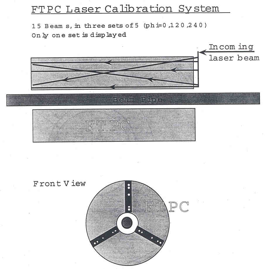
Schematic drawing of the distribution of the laser beams from Box D to the three insertion rods and a monitoring camera (CCD2) on the face of the FTPC. The components indicated inside Box D are not equivalent to the current design.
 

Schematic drawing of the components inside Box D. 5% of the intensity are reflected out of the beam for observation by a CCD camera (CCD 1), which supervises the  location of the beam upon arrival at Box D. A mirror with a remote controlled picodriver provides a last possibility to adjust the direction of the beam, supervised by CCD 2. Two small pickoff mirrors then reflect parts of the beam to two insertion rods, the remaining part continues on to the third insertion rod. Box D is designed at BNL by Daniel Cebra and Alexei Lebedev.


3d-view of the Box D design: