Data acquisition for the drift monitor
The acquisition of the data for the drift monitor system is performed by a
PC (PCSTARB in Munich) running Labview. The signals are read out
by an ADC card installed in the PC
(PCI9812 from NuDAQ, the
manual is also available on the web).
The drivers for the card and a preliminary
(working) version of the acquisition code are in the PC under the
directory:
D:\users\gaspare\drift monitor\labview
At the moment (6/00) the system is being tested using a pulser setup to
generate a "standard" signal to be sent at the input of the preamlifier.
A standard signal is defined as a voltage step of about +200mV with a
rise time of less than 20ns across a 1pF capacitor.
With this setup the signal at the input of the preamlifier has
an amplitude of few mV, a rise time (10%-90%) of about 10ns and a fall
time (100%-50%) of about 300ns and approximates well the signal
collected from the tube of the proportional counter.
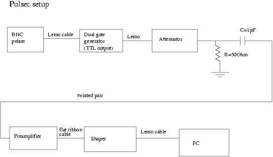
The pulser setup illustrated in the following picture is used
in order to trigger a scope and the PCI card continuously:

Setup parameters:
pulser period:
dual gate generator:
PCI 9812 card
The relevant features of the card are:
12 bits analog resolution;
4 input A/D channels and one digital trigger channel;
five trigger modes: software trigger, pre-trigger, post-prigger,
middle-trigger and delay-trigger (look in the manual for more details);
the sampling frequency is software selectable up to 20MHz. Nevertheless a
loss of data (depending on the data throughput) is possible at the
maximum frequancy. A 10MHz setting is therefore recommanded;
the A/D conversion starts about 350ns after a trigger event and this
introduces a jitter that has to be taken into account in the analysis;
two input ranges +1V/-1V (select 10 on the Labview driver) or +5V/-5V
(select 2 on the Labview driver) are software selectable.
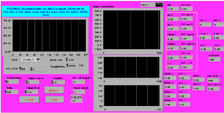
How to operate the data acquisition program for the drift monitor.


