Last update   05/28/2000
Hardware documentation for setup at BNL

           Main Page                                           FTPC  HVC  HVAFEE-LV Daq  GasWater Laser


FTPC I :
                                      Located:   In tent Bldg. 1006
                                         Status:
                                                        Mounted on wheels cable tree not connected.
                                                        Gas system  can be conected  see logbook.
                                                        HV,LV is part time connected look to current status in logbook.

                                                        FC tested with HV to -15 kV FC-bot at -150 V .
                                                       All 30 RC Tested between 50 - 1950 V
                                                       All seem to be stable no spark neither for FC nor RC's.

                                                                         Box D mounted,  laser fingers mounted at 4 , 7 and 11 o'clock.
 

                                     ToDo:  Laser adjustment , mount cable tree, reduce O2  < 10 ppm  in system with compressor
                                                     connect water system, mount RDO,Test chamber with Laser and Cosmic .


HV - Heinzinger  (Cathode):

                                                   Located : Rack in tent
                                         Status: Approved, working , Tested to -20 kV stand alone, remote control possible RS232 C

                                         Max Volt :=                            - 20 kV

                                         Def.  test Volt =                      -15 kV
                                       FC -current def. voltage=   0.22 mA

                                      Operational voltage  =          -10 kV
                                       FC-current                =           0.14 mA


Anode -Voltage C.A.E.N.:

                                               Located :   Rack int tent
                                        Status:   Approved, voltage working , Tested to 2 kV standalone.

                                                        Serial RS 232 C did not respond to command NO remote control at the moment.
                                                        Up to now operate by hand.

                                                        Remote control established 25.05.00.
                                                        Can be operated by remote with minicom.

                                     Caution (Display shows voltage *2 for positive voltage and voltage *10 for negative voltage)

                                        Max Volt  :=                                 +2 kV
                                        Test ramp for RC ==>               50,500,1000,1500,1600,1700,1800,1900,1950 [V]
                                      Settings:
                                                          Trip time   =                  0.2 s
                                                           I0                =                  1 micro A.
                                                           URamp      =                 10 V/s

                                  How to connect the chamber:
                                                                                       1) Check HV connections at the back there should be two modules
                                                                                            installed one 4 channel negative voltage supply max. -200 V and one
                                                                                            4 channel module for positive power up to + 2000 V.
                                                                                        2) The negative, should have one connection to a box behind the
                                                                                             chamber which is splitted into 4 connectors which should be at the
                                                                                             chamber (LEMO). This voltage defines FC-bottom should
                                                                                              be -150 V.
                                                                                        3) The positive power supply is to apply the anode voltages,
                                                                                              before you can do that you have to connect the open ends of the
                                                                                              anode cables at the chamber to one of the connector
                                                                                              boxes from the cable tree. After this, you have to connect an SHV
                                                                                              cable between the power supply and the box at the chamber.
                                                                                          4) Use in both cases the upper channel to connect. This corresponds
                                                                                               to channel 4 & 8  at the C.A.E.N. (4 is anode , 8 is FC bot).

                                                                                     DON'T  WORK AT THIS SYSTEM  WITH TRY AND ERROR
                                                                                     FOLLOW THE INTRUCTIONS BELOW
                                                                                     IF THEY DON'T WORK ASK OR LOOK IN THE MANUAL
                                                                                     YOU CAN DESTROY THE WIRE CHAMBERS  !!!!!!!!!!!!!!!!

How to operate C.A.E.N. by hand :

                             Initialize + 1 st. setting + turn ON:
                                                                                            1) Turn C.A.E.N .on.
                                                                                               2) Turn HV switch in up position.
                                                                                               3)  Look to the right end of the create  there is the coding for
                                                                                                     operating the C.A.E.N.
                                                                                               4)  To select channel which and turn on HV type:

                                                                                                      F0 #  the (#) act as an enter.
                                                                                                         4 #  select channel 4.

                                                                                                        F1 #   set V0 voltage.
                                                                                                       100 #  set +50 Volt.

                                                                                                        F10 # Turn voltage on by 10 V/s ramp.

                                                           To increase voltage :

                                                                                                           F1 #   set V0 voltage.
                                                                                                       1000 #   set +500 Volt.
                                                        To turn voltage OFF:
                                                                                                          F11 # Turn voltage off by 10 V/s ramp.
 

How to operate C.A.E.N. by remote :

                                                         Make sure that serial connection between fonda and C.A.E.N. is established.

                                                            Login :             fonda.star.bnl.gov
                                                                user:           see Daq docu.
                                                         How To:             Start xterm.
                                                                                      Type:
                                                                                               prompt>  minicom

                                                                                      After this turn ON C.A.E.N. .
                                                                                      Turn also the HV switch inthe UP position.
                                                                                      You should get in the minicom window the control pannel
                                                                                       for the C.A.E.N.
                                                                                       Type the character for the desired operation.
                                                                                       In most times it's  "b"  to change a setting for a given channel.
                                                                                       Inside this menue you have to  select the channel by typing "a",
                                                                                       followed  "CH04 (enter)" for example channel 4 (it's case sensitve) .
                                                                                       With "c" you can change the voltage .

                                                                                     IT IS NOT LIKE THE OPERATION BY HAND
                                                                                       THE VALUE YOU WRITE IS THE CORRECT
                                                                                       VOLTAGE  NO FATCH FACTORS ARE MULTIPLIED.

                                                                                      With "n" you turn the voltage ON or OFF.
                                                                                         If the voltage is on and you higher teh set value it will automaticly
                                                                                         ramp the voltage.
                                                                                         Thats all.

                                                    Quit minicom:      After you turned OFF all voltages and turned OFF the C.A.E.N.
                                                                                        you can quit minicom by typing:
                                                                                                                                                     Cntl -A  Z
                                                                                                                                                      x


                        Comments :
                                           Control unit for RS 232 C broken.


FEE Low-Voltage:

                                             Located :   Rack in tent
                                    Status:      Approved,working  tested with first FTPC-RDO.
                                                        Changed current in + and - channel bye removing 2 fuses for middle channel.
                                                        Former outgoing voltage = -9.89, +9.82 [V]
                                                        Now                                      =  -8.7 ,  +8.6   [V]

                                    How to operate:
                                                                  1)  Make sure that the LV-cable is connected to RDO an that the connector at
                                                                         the board  is correctly inserted, it's very stiff so be carefully.
                                                                   2) Check that the water system is running  and cooling (circulation on).
                                                                   3) Turn low voltage power supply on.

                                    ToDo : Add 0.1 Ohm 10 W resistor in each line to reduce voltage.


DAQ:

                                       Status: Single system is running in the tent using standart DAQ VME-Create
                                                       Consists of :
                                                                               1)  MVME 2300  PPC  (6U)
                                                                               2)  1 Receiver (9U)
                                                                               3)  1 TCD        (9U) ==> VME address 0x2300000 (negtive logic on board)

                                                                                                          4) 1 FTPC  RDO  with 15 FEE-boards on chamber connected

                                                    How to operate the DAQ:
                                                                                              Make sure that all connections are made
                                                                                               Checklist :
                                                                                                                    a) Fiber between receiver and RDO (receiver Fiber ok )
                                                                                                                    b) RDO is powered up and cooling is on.
                                                                                                                    c)  Trigger cable is connected
                                                                                                                    d)  No red light at RDO.
 

                                                                                          Login    :=     fonda.star.bnl.gov
                                                                                           user      :=     daq
                                                                                                                         passwd :=     ask Andreas (This is not the password !!!!!!!!!)

                                                                                           Get an xterm:
                                                                                            Type :
                                                                                                       prompt>  minicom

                                                                                            Reboot MVME 2300 by reset or turn create ON if OFF
                                                                                            (It's idiot proved !!!!!!!!!!!!!)

                                                                                           In the minicom window :
                                                                                            Type : (If rebooted)
                                                                                                                               Ftp01>  m 0x2300002,2  (enter)
                                                                                                                                              2300 0002 |  4     (.)

                                                                                                                               Ftp01> daqSendConfig  0,0,3,0x1001 (enter)
                                                                                                                               Ftp01> daqRunStart "Filename" (enter)
 
                                                                                                                  a)  Tigger by hand
                                                                                                                               Ftp01> trgFTPC 10,2  (enter)

                                                                                                                  b)  Trigger TCD by TTL min 20 us long

                                                                                              If finished type :
                                                                                                                           Ftp01> daqRunStop (enter)
                                                                                              File is located:
                                                                                                                         Computer  := daqman, Daq.star.dnl.gov
                                                                                                                          Directory := /data/scatch/FTPC

                                                                                             Close minicom window by typing:
                                                                                                                                                             Cntl -A   Z
                                                                                                                                                              x

                                                                                                You are done  or system is  dead !!!!!!!!!!!!!!!!


Gas  system:
                                         Located: STAR  Gas - room Bldg. 1006
                                         Status:   Approved, working , tested.

                                                     Calibration for oxygen sensor  :
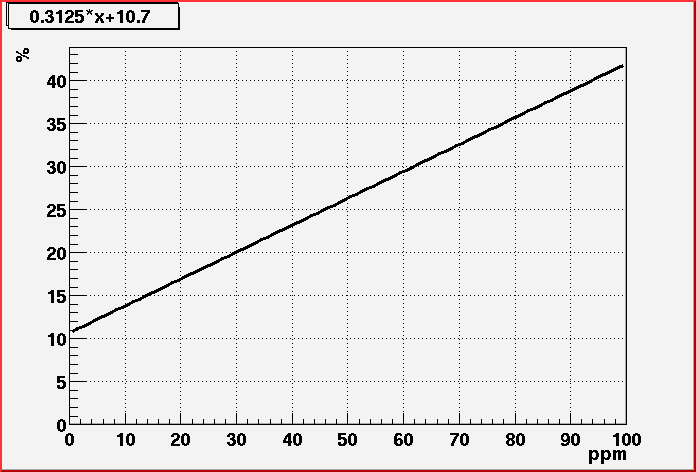
                                                                                                       Linear function  ==>  ppm = 0.3125 * x % + 10.7 %
                                                                                                                                                3.3 ppm ~ 1 %

                                       This is a first  (beta) calibration with 2 points the error is in the range of 3-5 ppm.


  How to operate the System :
                                                           HOLD ON  !!!!!!
                                                             WITH  A WRONG OPERATION  OF THE GAS SYSTEM YOU CAN
                                                             DAMAGE  THE FTPC  GAS WINDOWS AND READOUT CHAMBERS.
                                                             READ THE  INSTRUCTION BELOW CAREFULLY AND CHECK
                                                             EVERY  PARAMETER  OF THE SYSTEM BEFORE CHANGING IT.
                                                             HAVE A LOOK TO THE DRAWING OF THE GAS SYSTEM BELOW.
                                                             CONTROL THE CO2 BOTTLE OUTSIDE AND LOOK TO THE ARGON LINE.
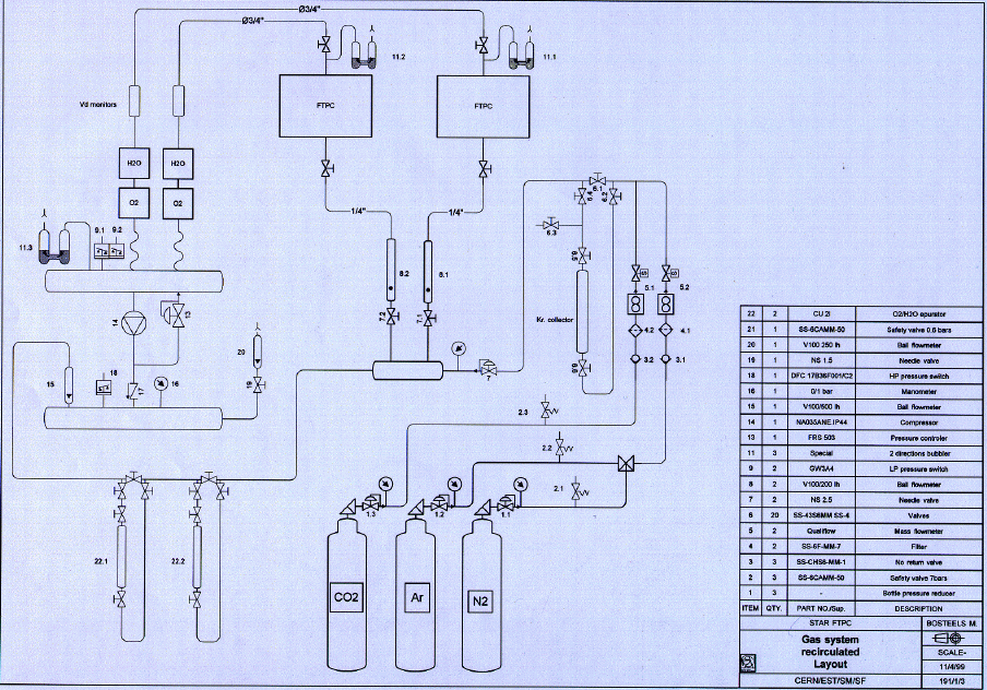
  Schematic drawing:
 

:

                                 Principle  function :
                                                               Gas system is connected to the TPC Ar-dewar and a CO2 bottle.
                                                                  In both lines a valve control the flow which is monitored by the display layers.
                                                                 These two incoming lines are joined at a point and only one line goes to a small
                                                                  mixing volume (a) ~ 5-6  l. In front of this volume a pressure measurement is done
                                                                  (small gage G1) were the pressure can be adjusted by a needle valve.
                                                                 This small volume (a) has two incoming and two outgoing connections.
                                                                 The first incoming is the fresh gas the second one is the cycled gas from the
                                                                  compressor side. The two outgoing lines are connecting through two needle valves
                                                                  controlled flowmeters to the FTPC"s (A+B).
                                                                  The return line from both FTPC's are connected to the back of the gas system
                                                                  in which the oxygen and water content  measurement is done.
                                                                  Later also the drift velocity measurement will be
                                                                  done in this lines. After this, both return lines end in a volume (b) of ~ 10 l.
                                                                  At this volume (b) the low and high pressure measurement is performed,
                                                                  which is monitored  at the status and system setting layer of the display.
                                                                 Also at this volume (b) the bubbler is installed, which you can see inside the gas rack,
                                                                  where the gas is floating  into the gas room.
                                                                  Behind this volume the compressor is connected which cycle the gas through the
                                                                  system. After the compressor it's again a volume (c)   of ~10 l.
                                                                 At this volume (c) the big gage (G2)  is connected and measures the
                                                                  pressure at this point.
                                                                  Here also the two flowmeter (20,21) are connected (purge lines)
                                                                  which let the gas flow out of the system into the gas room.
                                                                  If they are closed the gas has to go through the bubbler to leave the sytem.
                                                                 Again a pressure measurement is performed at this point which you can see on the
                                                                 display.  The last connection to this volume (c)  is the flowmeter wich measures the
                                                                 circulation flow in the system which is connected to the first described volume (a).
                                                                 At this last connection line between volume (c) and (a) the cleaning system
                                                                  is installed were the gas can be forced by valves to go through this cleaning tubes.
 

                                      Check Gas :
                                                              Argon line  manometer behind gas system should have between 1.5 - 2 bar.
                                                                 CO2 outside manometer has to be opened look for proper pressure reduction.
                                                                 The CO2 bottle shows always 40-60 bar due the phase diagram. If it's falling
                                                                  you need a new bottle soon. Outgoing pressure should be between 1.5 - 2.5  bar,
                                                                  not more.

                                           Turn on:
                                                              Turn the big red switch on, it's located on the left side above the display.
                                                               System should wake up display should boot processsor.
                                                               All LED at the buttons should flash red.
                                                               Press reset button.
                                                               The flashing of the LED should disapear.
                                                               Only the upper left LED will flash permanently.

                              Processor Unit :
                                                          The processor unit  consists out of 3 parts :
                                                               1)  Display for the layout, valve settings and measured parameters.
                                                               2)  Steering + Layer bottons.
                                                               3)  Processor and logic to steer the system by program

                                                               With the 1+2  part you are able to monitor,control and change system parameters
                                                                which are used and realized by part 3.
 

                                              Status:
                                                             After turn on the display should show the STATUS layer (a) of the actual situation.
                                                              If not press the STATUS button on the left side of  the display.
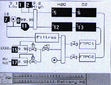
   Display (a): Status


                            System settings:
                                                              Change the display layer by pressing the SYSTEM SETTING button.
                                                                Now you should see picture (b). The settings will be different
                                                                Turn flowmeters on by pressing the button nearest to the right.
                                                                It should change on the display from OFF to ON (14).
                                                                Normal behavier is  an overpressure at the outgoing valve black square flashing (2)
                                                                on top of the system sketch (b).This should disappear after a few minutes when the
                                                                pump is started.

                                                                                     If you want to circulate the gas with the pump  you have to start the pump.
                                                                 Check which case you want below.
                                                                 It's the button above the flowmeters on the display turn it ON (13).
                                                                 Pump should start.

                                                                 If you want to have Ar/CO2 (50/50) you have to activate the CO2 in the system.
                                                                 Press on the left side of the system the button nearest to the CO2 box (10) in the
                                                                 display. The area in the display must flash (10). The value is 0.0.
                                                                 Select with the numeric bottons 100 and press enter. The system is in an
                                                                 Ar = Master and CO2 = Slave mode.  So 100 % CO2 means equal parts Ar and CO2.
                                                                 After this you should see in the CO2 box (10)  at the display a 100 %.

                                                                 Do NOT change the pump speed (9) it's set to 55 %. This is an optimum.

                                                                 Adjust the flow meters described below for the case you want to run the
                                                                  system .

                                                                 Take your time, think about what are you doing.

                                                                 Watch the gages on the right gas rack. The upper left gage shows you the
                                                                  pressure after the compressor (system picture #14)  behind the FTPC's
                                                                  the small gage in the middle right shows you the pressure before  the FTPC's
                                                                  at the gas system.The difference measures  the  pressure gradient in the system.
                                                                  Both should show the same pressure (~ 300 mbar) then  dp ~ 0,
                                                                  so the system circulate  with no (large) leak . Look at the bubbler inside
                                                                  the gas rack (right side), they should start bubbling after a few minutes.
                                                                  Look to the chamber, is the pressure window  starting to arch.

                                                                  Change the display layer by pressing STATUS.

                                                                   If dp != 0  and the pressure at the small gage is below the one at the large gage
                                                                   you have to open the valve above (big black knob) the small gage until dp=0.
                                                                   Or vice versa.

                                                                   At the same time you should see at the display that the opening of the valves
                                                                   for the Ar or CO2 line should open or close  (a 15,17) depending what you
                                                                   are doing at the pressure. Make sure that the value at the display is below
                                                                  100 % (max. 99.7 %) .
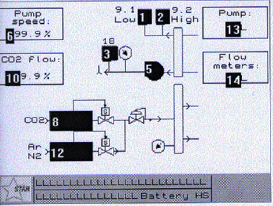
 

    Display (b) : System settings


                              Check Flowmeters:
                                                                                        The flowmeters are located on the upper right side of the gas system.
                                                                   There are five of them in a row all calibrated to air so you need to calculate
                                                                    the actual flow of your gas by multiply with a fatch factor see tables below:

                                                                   From the left :
                                                                                                  1. Purge up to                           0-40   l/h
                                                                                                  2. Purge between                   40-250 l/h
                                                                                                  3. Flow FTPC A                      0-250 l/h
                                                                                                  4. Flow FTPC B                       0-250 l/h
                                                                                                  5. Circulation in the  system 0-500 l/h

 Air              [l /h]   Fac.    Purge (0-40 l/h)  Ar  [l/h]   Fac.  Purge +FTPC's  Ar [ l/h]  Fac .         Circulation      Ar [l/h]
                 25               10   0.8431                                       8.42   0.8425                               21.06
                 50              20   0.8395                                     16.79   0.8385                               41.92  0.8405                                       42.25 
                 75               30   08378                                      25.14    0.8349                                62.62
                100            40    0.8346                                     33.37   0.8332                                83.32  0.8346                                       83.46
                125      0.8314                              103.93
                150   0.8300                              124.5  0.8317                                     124.76
                175   0.8297                              145.2
                200   0.8290                              165.8  0.8295                                      165.9
                225   0.8283                              168.8
                250   0.8278                              206.95   0.8282                                     207.05


 Air          [l /h]   Fac.  Purge (0-40 l/h)   CO2 [l/h]   Fac.    Purge+FTPC's  CO2 [l/h]  Fac.         Circulation       CO2 [l/h]
                 25             10  1.1013                                       11.02  1.0955                                 27.39
                 50             20  1.0170                                       20.34  1.014                                   50.7  1.0769                                        53.85
                 75             30  0.9637                                       28.90  0.9577                                71.83
                100             40  0.9334                                       37.34  0.9272                                92.72  0.9682                                        96.82
                125   0.9007                              112.59
                150  0.8846                              132.69  0.9198                                       137.97
                175  0.8777                              153.6
                200  0.8674                              173.48  0.8847                                       176.94
                225  0.8587                              193.21
                250  0.8529                               213.23  0.8630                                       215.75

 
 Air            [l /h]   Fac. Purge (0-40 l/h) ArCO2 [l/h]  Fac. Purge +FTPC's  ArCO2 [ l/h]  Fac.    Circulation     ArCO2 [l/h]
                 25            10  0.969                                   24.23
                 50             20  0.9263                                 46.30
                 75            30  0.8963                                 67.21
                100           40  0.8802                                 88.02
                125  0.8661                               108.26
                150  0.8573                               128.6
                175  0.8537                               149.6
                200  0.8482                               169.64
                225  0.8435                               189.79
                250  0.8404                               210.09

                                 If all settings are ok you will read at the lower part of the display .
                                 Mode : Run
                                 System Ok

                                 If the pump if OFF you will read at the lower part of the display .
                                 Mode : Run
                                 System failure
 

Cases:

                                                                             Hints how it should look like !

                                                          A)   Gas system  stand alone or with short circuit in tent.
                                                                                          You have to make sure that the short circuits are installed.
 

                                                                        Gage 1:     =  ~300 - 400 mbar
                                                                        Gage 2:     =  ~300 - 400 mbar
                                                                                  dp     =   ~ 0
                                                                         Ar valve  =   max . 99.7 %
                                                                         Pump        =  OFF/ON
                                                                         Flowmeter = ON
                                                                         Purge         =   closed or 100 -200 l/h  (Air)
                                                                         FTPC A    =  closed
                                                                         FTPC  B    =  closed or 100-200 l/h  (Air)

                                                                         If  purge valve is closed all the gas has to flow through the
                                                                         bubbler to leaf the system.
                                                                         If the pump if OFF you will get a warning high pressure on the display.
                                                                         You can ignore this because it measures the pressure in volume (b) which
                                                                          is if pump is OFF at an higher pressure due to the fact, that the
                                                                          gas coming from the short circuit is now filling this volume
                                                                          and can leave it only, through the bubbler.
                                                                          If the chamber is connected look to the hight difference in the
                                                                          bubbler it tells you about the pressure in the chamber, ~1 cm difference against
                                                                          normal athmospheric pressure  ~1.5 mbar. Don't let it go above 5 mbar.
                                                                          Look to the schematic drawing. If you open the purge flowmeter
                                                                          the high pressure warning will at some point disapear.

                                                           B)   Gas system with chamber in purge mode.

                                                                        Gage 1:         =  ~300 -400  mbar
                                                                        Gage 2:         =  ~300 -400  mbar
                                                                                  dp        =   ~0
                                                                         Ar valve     =  max.   99.7 %
                                                                         CO2             =  max.   99.7%
                                                                         Pump           =  ON/OFF
                                                                         Flowmeter  = ON
                                                                         Purge            =   100 - 200 l/h  (Air)
                                                                         FTPC A      =  closed
                                                                         FTPC  B      =  100 - 200 l/h (Air)

                                                                         At the circulation flowmeter (CF) you should see the
                                                                         difference between the purge flow (PF)  and the FTPC B (FFB) flow.
                                                                                             As an example:
                                                                                                                          PF         ~100 l/h
                                                                                                                          FFB      ~150 l/h
                                                                                                                          CF          ~50 l/h
                                                                                            In a purge configuration you normaly  have a higher purge flow than circulation
                                                                      because you want to get the system ready to operate.

                                                             C)   Gas system with chamber in run mode.
 

                                                                        Gage 1:         =  ~300 mbar
                                                                        Gage 2:         =  ~300mbar
                                                                                  dp        =   ~0
                                                                         Ar valve      =  ~34%
                                                                         CO2 valve   =  ~34 %
                                                                         Pump            = ON
                                                                         Flowmeter   = ON
                                                                         Purge           =   50  l/h  (Air)
                                                                         FTPC A      =  closed
                                                                         FTPC  B      =   150  l/h  (Air)
                                                                         Circulation  =  100 l/h

                                                                                              Make sure that sill gas is goint through the bubbler that the chamber is operated
                                                                       at a small overpressure (2-3 mbar).
                                                                       As an example:
                                                                                                                          PF         ~ 50 l/h
                                                                                                                          FFB     ~ 150 l/h
                                                                                                                          CF         ~ 50 l/h
                             Turn OFF :
                                                          Change back from status display to system settings display.
                                                            Stop first the pump  if it's ON by pressing the botton on the right side of the display.
                                                            In the display you should see an OFF at the pump position.
                                                             Now you can turn off the flowmeters the same way.
                                                            Again you should see an OFF at the flowmeter position.
                                                          Now you can turn OFF the big red switch in the upper side of the gas system.
                                                            The system should shut down completely.


Water system:

                                         Located:  In tent near FTPC I

                                       Status:   Approved, working, tested.

                                      How to operate :
                                                                                     DON'T  WORK AT THIS SYSTEM  WITH TRY AND ERROR
                                                                                     FOLLOW THE INTRUCTIONS BELOW
                                                                                     IF THEY DON'T WORK ASK OR LOOK IN THE MANUAL
                                                                                     YOU CAN DESTROY SENSITIVE ELECTRONICS

                                                                         0) Make sure that system is at normal pressure 1 atm. (Large gage at 0 !)
                                                                               If not,  purge system by opening purge switch to open and wait until large
                                                                               gage is stable around 0. Move purge switch  to position close.
                                                                               If you want to cool down, you have to open the valves for the chill water at
                                                                                the back. Two at the wall two dirctly behind the system.They are open if the
                                                                                lever shows in direction of the tubes.
                                                                          1) Turn on red switch on the left. (Light is on !)
                                                                          2)  Wait 10 min. that pump starts pumping tank  to -500 mbar.
                                                                                Both gages (small  for Tank , large for circulating  System)  has to be around
                                                                               -500 mbar.
                                                                          3)  Wait 2-3 min.  the pressure at the lage gage should not fall in this time then
                                                                                 the system is tigth enough to start.
                                                                           4)  Start circulation by pressing the green button (left side)  the button is active
                                                                                 if  it's out  and it 's inactive if button in. (Light dosn't work)
                                                                           5) If circulation is started large gage should go up arount  -100 mbar.
                                                                           6) The pressure is adjustable due to the flowmeters in the middle left.
                                                                                Up to now only  right circuit is used by RDO. The left one is an short circuit
                                                                                behind the water system.
                                                                           7) Watch to the temperatures at the display the green on top one tells you
                                                                                  the actual temperature in the circulating system the orange
                                                                                  one below is the set value. If the differenz between this two
                                                                                  values if +- 1 C the alarm sign at the display is on (red). This should
                                                                                  disapear  if the water temperature is falling within the range.  To
                                                                                  change the set value  you have to read the manual.

                                                  ToDo : Fix light for circulation.


LASER:
                                        Located:  In the tent.

                                        Status:  Approved, UV working , testedn adjusted to chamber .
                                                       Started adjusting Box D on FTPC I.


 Top