
The reponsibility of the PMD experts is to keep an overall vigil on all the systems like the gas system, the high voltage, low voltage, PMD movements etc. If the detector operator in the control room faces any problem running your detector he'll call an expert, that's YOU. So please go through the following document very carefully.
1. Keep an eye on the report on PMD gas parameters given by the shift
crew.
2. Check the gas panel and gas bottle everyday.
3. Replace the running gas bottle with a new one.
4. Maintain the stock of gas bottles and order new bottle.
How to change a gas bottle:
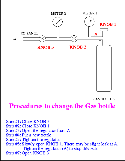
The running gas bottle should be replaced with a new one when the reading on the meter fixed with the bottle (METER1, look at the figure below) goes below 200. Don't wait till it reaches zero, that causes harm to the health of the bottle as well as your detector.
There is a funny story about something you learnt in High School. In winter the CO2 in the bottle, kept in the gas shed outside the assembly building, gets frozen. So please bring a new bottle inside the AB and keep it near the running bottle at least a day before you put it (to let it warm up).
Before you do anything, check that PMD cathode HV is OFF . Now if you're ready to change the bottle then follow the procedures written below:

You'll see a yellow tag hanging on the running bottle which says "IN USE" at the bottom. Tear it away so that the tag says "EMPTY". Follow similar procedure for the tag on the newly added gas bottle so that it says "IN USE" (I hope I'm clear enough).
| Slot 0, channel 0 | pmdhv:SUB_RD_V1_1:0.E |
| Slot 0, Channel 1 | pmdhv:SUB_RD_V1_1:0.F |
| Slot 0, Channel 2 | pmdhv:SUB_RD_V1_1:0.G |
| Slot 0, Channel 3 | pmdhv:SUB_RD_V1_1:0.H |
| Slot 0, Channel 4 | pmdhv:SUB_RD_V1_1:1.E |
| Slot 0, Channel 5 | pmdhv:SUB_RD_V1_1:1.F |
| Slot 0, Channel 6 | pmdhv:SUB_RD_V1_1:1.G |
| Slot 0, Channel 7 | pmdhv:SUB_RD_V1_1:1.H |
| Slot 0, Channel 8 | pmdhv:SUB_RD_V_1:0.E |
| Slot 0, Channel 9 | pmdhv:SUB_RD_V_1:0.F |
| Slot 0, Channel 10 | pmdhv:SUB_RD_V_1:0.G |
| Slot 0, Channel 11 | pmdhv:SUB_RD_V_1:0.H |
| Slot 1, Channel 0 | pmdhv:SUB_RD_V_1:0.I |
| Slot 1, Channel 1 | pmdhv:SUB_RD_V_1:0.J |
| Slot 1, Channel 2 | pmdhv:SUB_RD_V_1:0.K |
| Slot 1, Channel 3 | pmdhv:SUB_RD_V_1:0.L |
| Slot 1, Channel 4 | pmdhv:SUB_RD_V_1:1.E |
| Slot 1, Channel 5 | pmdhv:SUB_RD_V_1:1.F |
| Slot 1, Channel 6 | pmdhv:SUB_RD_V_1:1.G |
| Slot 1, Channel 7 | pmdhv:SUB_RD_V_1:1.H |
| Slot 1, Channel 8 | pmdhv:SUB_RD_V_1:1.I |
| Slot 1, Channel 9 | pmdhv:SUB_RD_V_1:1.J |
| Slot 1, Channel 10 | pmdhv:SUB_RD_V_1:1.K |
| Slot 1, Channel11 | pmdhv:SUB_RD_V_1:1.L |
Procedure :
Before approaching the motor control system, call Ralph Brown (x 7775), this is extremely important.
1) Switch power ON
2) Choose speed by speed selector switch:
Normal : around 3cms/sec
Slow : around 2cms/sec
Slower : around 1cm/sec
3) Girder movement:
Press the push button marked Girder-E or Girder-W (Red buttons) to move the entire girder with the detector planes in the E-direction or W- direction. GREEN indicator comes on when in motion. RED indicator turns on when the limits are reached and the movement automatically stops.
4) PMD North plane movement:
Press the push button marked PMD North (Green) - North button for northward movement and South button for southward movement. GREEN light comes on when the motors are moving, RED comes on when the limits are tripped.
5) PMD South plane movement:
Same as above. Choose push button marked PMD South.
CAUTION: DO NOT operate all the motors simultaneously as this may overload the power supply.
NOTE: When both E & W switches are pressed together, only East movement is actuated by the logic. Similarly when N & S switches are pressed together only north movement is turned on.