The Photon Multiplicity Detector (PMD) in STAR is a preshower detector consisting of an array of tiny hexagonal gas proportional counters with a mixture of Ar and CO2 (70%-30%) as an operating gas. The common wall of the copper cells form the cathode and a thin tungsten wire passing axially is the anode. When charged particles enters into the chamber it ionizes the gas and the ions are collected by the anode. A potential of ~1.5 kV is applied to the cathode to generate the field.
The detector has two planes called CPV and Preshower with 12 supermodules each. Each supermodule has got one commom HV suppply for the entire cathode for that supermodule. This way we need 24 HV channels for the whole detector.
PMD uses LeCroy 1454 mainframe with 1461N cards for HV. The mainframe has two cards in Slot0 and Slot1 each with 12 channels (chn0 - chn11) for CPV and Preshower plane respectively (See List of HV cables for PMD for the cabling scheme).
When the MVME CPU for the HV control boots up for the first time, it takes the demand voltage values for all channels from a file called demand file.
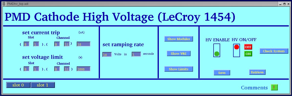
There are two windows for the HV controls for PMD. The main window allows the operator to set the current and voltage limits collectively for many channels as well as for a particular channel. It also allows to set the ramp rate and put the HV ON and OFF. The two buttons at the bottom left corner lets the operator open the slotwise windows. To change any entry on this window the operator has to click on a particular entry box as well as keep the mouse on the box to keep it active. After making any change you have to hit the "Enter" key to register the new value.
The PMD High Voltage control main window should be on the PMD control monitor . If it is not there then login to slow control state machine (sc3.starp.bnl.gov), username and password should be available with the shift leader. Then type "PMDhv" on that window.
On the extreme left column the top entry is to set the trip current for different channels. The two slots can be chosen together as 0-1 or for a particular slot one can chose as 0-0 or 1-1. Similar is true for channels. The value of the trip current is taken as -ve and the unit is is uA. the default value is -50 uA for all channels.
The next entry below the trip current setting is to set the software limit of High Voltage. The 1461N modules has a provision of setting a hardwrae limit through a pot on the front panel of the card. But for the safety of the detector there is one more option of setting a software limit to each differnt channel through this entry. Once this limit is set the module will not go beyond the limit even if the demand value is set higher than the limit value. The limit can be set in a way similar to the trip current setting. The value of the limit is -ve and the unit is Volts. The default value is set to -1550 Volts for all channels.
The third entry is to set the ramp rate. One can go as low as 1 Volt per second. The default setting of the ramp rate is 10 Volts per second.
The next column shows six buttons.The actions of the buttons are
described below:
1. Show Modules: This shows how many cards are there in the mainframe.
2. Show V & I: This shows the present values of vopltage and currents for all
channels.
and the
bottom one shows the present setting of trip current and limit voltages
(hardware limits).
In the extreme right section there are two indicators. The left one is
to show whether the channels are enabled or disabled. If the green light glows
then all the channels are enabled. On the other hand if the red light glows
then one or more channels are disabled. The next indicator is for HV ON/OFF.
There are two buttons to put the supply ON or OFF. The red light keeps glowing
till all the channels reach there demand (or limit) voltages. This means the
green light glows only once the ramp up is successful.
There are three more buttons in this section of the window. The "Check
System" button checks the HV status and the trip status of the channels. The
"Save" button saves the current value of demand voltages in the demand file and
the "Retrieve" button takes the demand voltages from the last saved demand
file.
The two buttons at the bottom left corner allows the operator open the slotwise display of different channel information.
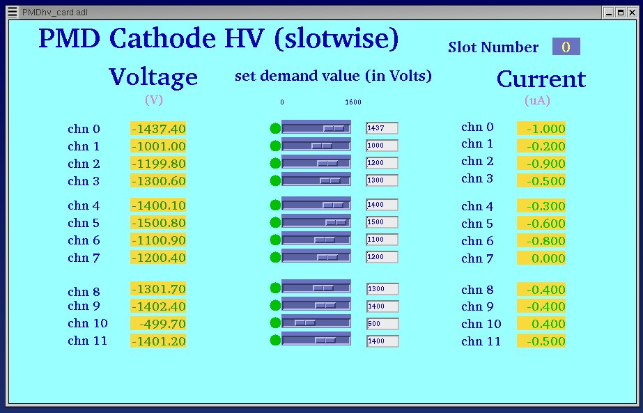
The operator is allowed to change the demand value through the entry
box or moving the slider left or right. The column on the left side shows
the voltmeters and the column on the left shows the ammeters for the different
channels.
If the indicator at the left side of the slider is red that means the readback
value of voltage differs by more than 20 Volts from the demand value.
There is an indicator on the left side of the voltmeters for each
channel to show the trip status of that particular channel. If there is no light
then the channel is alive. If the indicator turns yellow, the channel is tripped
due to any of the following reasons i) violation of supply limits, ii) votage
error, iii) violation of voltage limits. If the indicator turns RED then the
channel is tripped due to violation of current limit set by the user.
Clicking on the "Comments" button at the bottom right corner of the main window opens a xemacs window allowing the operator to write any comment on the operation.
Back to PMD basic procedures page