
As you already know, the S V T system test is well underway.
Here are a few preliminary results with current photos and graphics.
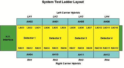
 System
test stand utilizing 4 detectors and 8 hybrid circuits plus 3 dummy detectors
and 6 dummy hybrids to simulate a full outer ladder. The stand is also
fitted with forced cooled air plus capabilities of water cooling for the
hybrids.
System
test stand utilizing 4 detectors and 8 hybrid circuits plus 3 dummy detectors
and 6 dummy hybrids to simulate a full outer ladder. The stand is also
fitted with forced cooled air plus capabilities of water cooling for the
hybrids.
 A
view of the transition board and circuitry for adjusting focusing voltages
and injector bias.
A
view of the transition board and circuitry for adjusting focusing voltages
and injector bias.
 The
high voltage interface board, carrier interface boards, 1 prototype signal
distribution cable (left) and 1 hand made cable, prototype signal and high
voltage cables.
The
high voltage interface board, carrier interface boards, 1 prototype signal
distribution cable (left) and 1 hand made cable, prototype signal and high
voltage cables.
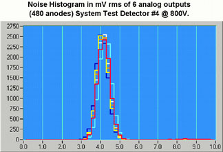 This noise
histogram is typical of all 4 detectors (24 analog outputs).
This noise
histogram is typical of all 4 detectors (24 analog outputs).
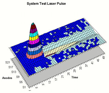
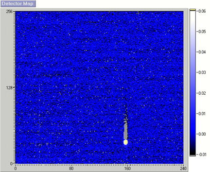 Full detector map (480 anodes
and 256 time buckets) showing a laser pulse. The scale on right indicates
pulse amplitude in volts after pedestal subtraction. The detectors were
powered to 800V. Note the PASA response function trailing the pulse.
Full detector map (480 anodes
and 256 time buckets) showing a laser pulse. The scale on right indicates
pulse amplitude in volts after pedestal subtraction. The detectors were
powered to 800V. Note the PASA response function trailing the pulse.
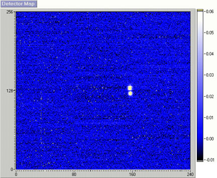 The same detector with the
laser located at the central divide.
The same detector with the
laser located at the central divide.
Page updated on 11-13-97 by Phil Kuczewski
Direct questions or comments to:
philk@bnl.gov lynn2@bnl.gov