FEATURES:
MODEL DTM-299 (Standard Version)
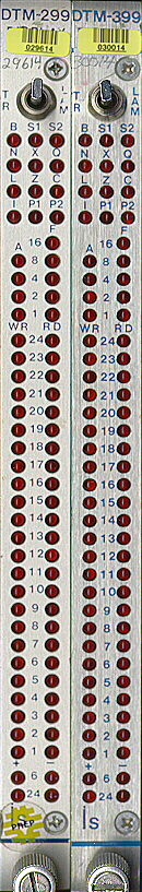
-Displays ALL dataway signal
-Both Track and Latch mode
-Manual LAM generation
-Read of previous dataway cycle
-Data and Status F, A, etc.
-Stretched display of B, Sl , S2, L
MODEL DTM-399 (Enhanced Version)
-Power supply failure detection
-Ambient temperature monitor
DESCRIPTION:
This series of Dataway Test Modules is designed for use as a low-cost diagnostic, test and display aid for troubleshooting CAMAC, from both a hardware and sottware viewpoint. Status and dataway conditions can be seen at a glance, also computer controlled systems can run self diagnostics through to the dataway level. (Confidence factor for system programmers)!
Front panel LED indicators display the status of all dataway signals in either Latch or Track (continuous) mode. Write data, control signals, and status for the previous dataway operations may be read back for system self diagnosis. A front panel manual LAM switch is also available to test the crate and software LAM handling capability.
In addition to these features the MODEL DTM-399 includes monitoring of ambient temperature and the four standard CAMAC power supplies. Should a preset limit be exceeded by high ambient temperature, a voltage failure, current spike or power supply oscillation a LAM will be generated. The detection and logic circuitry is powered by voltage steering and any supply may fail without affecting the modules operation.
COMMANDS:
        DTM-299

NA[O]F[O]  Read data       Q,X = 1
   Reads previously Latched write data onto Dataway
   read linds.  Rl-R24

NA[O]F[l]    Read status    Q,X = 1
   Reads previously Latched  status, function code,
   subaddress, etc. onto Dataway read lines, plus
   reads position status ot front panel switch.

NA[O]F[8] Test LAM     X = 1
  Test LAM status, Q=1 if set

NA[O]F[10] Reset LAM   Q,X=l
  Resets LAM request.


DTM-399 [ADDITIONAL COMMANDS]

NA[O]F[l] Read Status     Q,X = 1

NA[O]F[24] Disable LAM    Q,X = 1       NA[O]F[26] Enable LAM     Q,X= 1


SPECIFICATIONS:

 SIGNALS DISPLAYED
 Latched  at  Sl
 Read          R(24)       Write         W(24)
 Function      F(5)        Subaddress    A(4)
 Stn.  No.      N           0 Response    Q
 Pl Bus        Pi          X Response    X
 P2 Bus        P2
 Latches  at   S2
 Initialize    z           Clear         c
 Stretched [200 MS]
 Strobe 1      s1          Strobe 2      S2
 Busy          B           LAM           L

 DTM-399 [ONLY]

 Temperature set point range:     25-600C
 Voltage set point range-.
 +6  =  +3 to  +6v                   +24  =  +21 to  +24v
 -6  =    -3 to  -6v                  -24  =     -21  to  -24v
 Continuous [Track]
 +/- 6 Volts  6(2)      +/-24 Volts   24(2)
 inhibit     l (1)
 Power Requirements
 +6V - 1 8 A Max
 - 6V. +/-24V - 16 ma.
 Operational Mades
 LATCH - Dataway signals are latched with the
 appropriate strobe
 TRACK - Real Time continuous display of data-
 way signals
 Mechanical
 Single width module

Minimum voltage excursion time for detection (voltage spike) = 1 usec
Reference stability = +/- .1 % 24 hours.