The LRS Model 380A Multiplicity Logic Unit for the first time allows easy generation of higher order multiplicity decisions from a large number of counter or chamber logic signals. The unit produces an output whenever N (or > N) out of M input pulses are present, where N is switch-selectable from 1 to 6, and M is any number up to 32. Two sets of outputs are provided, one set for the = N condition and one set for the > N condition. An additional analog summing output is provided giving an amplitude of -50 mV into 50 Ohm for each coincident input pulse and a duration equal to the overlap time of the coincident input signals. Since the unit can operate in an ungated mode, and does not require a master strobe signal, it is very useful in trigger pulse generation systems. In systems where a master trigger already exists (e.g., with wire chambers), the Model 380A may be operated in a strobed mode with either pulse or latched outputs. Input speed is compatible with normal 100 MHz logic and maximum output rate is determined by output width.
In the pulse mode, the duration of the = N outputs is preset to 20 ns, but is internally adjustable up to 50 ns. The duration of the > N outputs is front-panel adjustable from 25-100 ns and must be set equal to the maximum possible overlap time of the logic inputs. The > N outputs are generated approximately 12 ns after the > N condition is satisfied. The = N outputs appear somewhat later, approximately 8 ns after the end of the = N input condition, because of the logical necessity of waiting to insure no > N condition occurs.
A clear input is provided to reset the unit in the latched mode. For strobed operation, the veto is driven by a complementary logic signal which goes to zero volts during the strobe interval.
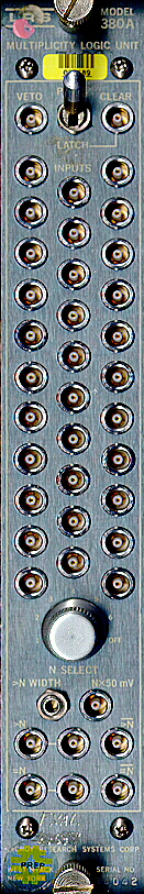
NIM Model 380A MULTIPLICITY LOGIC UNIT
SPECIFICATIONS
|
INPUT CHARACTERISTICS |
|
|
Logic Inputs: |
32; reflections < 7% for inputs of 2 ns risetime; input range - 650 mV to - 900 mV (NIM level); minimum input width 6 ns. |
|
Veto: |
Common to all channels; direct-coupled; - 600 mV or greater inhibits; impe- dance 50 Ohm; reflections < 7% for inputs of 2 ns risetime. Veto must overlap logic inputs. |
|
Slow (Bin) Gate: |
Via rear connector, with rear-panel On-Off switch; risetimes and falltimes ap- proximately 20 ns; quiescently above + 4 volts, clamping to ground inhibits; direct-coupled. |
|
Clear: |
NIM level; minimum duration 10 ns. |
|
OUTPUT CHARACTERISTICS |
|
|
> N Outputs: |
2 bridged negative outputs (quiescently 0 mA, - 32 mA during output); one complement (quiescently - 16 mA, 0 mA during output); duration variable from 25-100 ns by means of front panel-multiturn potentiometer in pulsed mode, dc level in latched mode. Must be set >= maximum possible overlap time of the logic inputs (since it serves to inhibit the = N outputs when present). |
|
N Outputs: |
2 bridged negative outputs (quiescently 0 mA, -32 mA during output); one complement (quiescently - 1 6 mA, 0 mA during output); duration 20 ns (internally adjustable) in pulse mode, dc level in latched mode. |
|
Risetimes and Falltimes: |
3 ns. |
|
Analog Summing Output: |
One; amplitude - 50 mV into 50 Ohm for each coincident input pulse; duration equal to the overlap time of the coincident input signals; impedance approx. 6 Ohm. |
|
GENERAL |
|
|
Coincidence Level Control: |
From 1 to 6 plus "off"; front-panel switch. |
|
Input Double-Pulse Resolution: |
< 1 0 ns. |
|
Output Double-Pulse Resolution: |
< 30 ns. |
|
Modes: |
Pulse or latched; controls output duration. |
|
Delay: |
Input-Output, 12 ns for > N output, 8 ns following end of = N condition for = N output. |
|
Packaging: |
In conformance with AEC standard for nuclear modules (AEC Report TID-20893); RF shielded AEC #1 module fitting 12/bin; dimensions 1.375 x 8.75 x 10 inches deep. |
|
Current Requirements: |
+ 6 V at 95 mA |