| STAR home | |
| TPC Pad Plane | |
| Maintenance | |
| Last modified: 10:35 Thursday 08-JUN-2000 | |
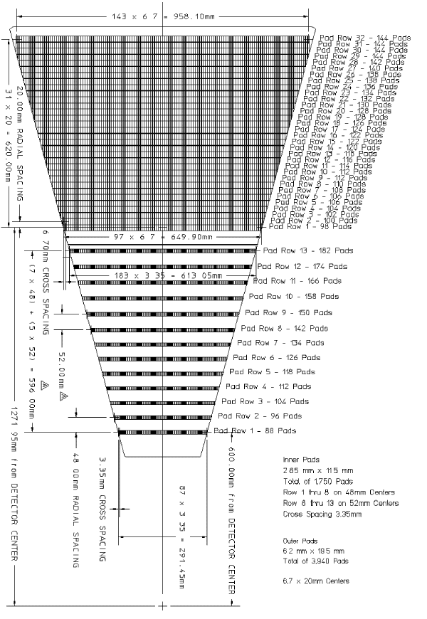
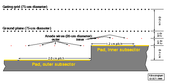
Nominal data on the TPC padplane (See figure: Postscript or GIF) is summarized for convenience, following a short introduction. The basic arrangement of the wires relative to the inner and outer pad rows is shown below schematically (however, the sensitive pads do not actually extend all the way to the ends of the subsectors, and the subsectors are separated by a gap):
| Subsector | Row | Radius (cm) |
Pads | Pad 1 fraction |
Pad 2 fraction |
Anode wires | Anode-wire termination |
Notes |
|---|---|---|---|---|---|---|---|---|
| Inner | 1 | 60.000 | 88 | 0.778 | 1.000 | 17 - 19 | Card 1 | 1 |
| " | 2 | 64.800 | 96 | 0.652 | " | 29 - 31 | Card 2 | 2 |
| " | 3 | 69.600 | 104 | 0.499 | " | 41 - 43 | Card 3 | " |
| " | 4 | 74.400 | 112 | 0.347 | 0.992 | 53 - 54 | " | " |
| " | 5 | 79.200 | 118 | 0.957 | 1.000 | 65 - 67 | Card 4 | " |
| " | 6 | 84.000 | 126 | 0.893 | " | 77 - 79 | " | " |
| " | 7 | 88.800 | 134 | 0.802 | " | 89 - 91 | Card 5 | " |
| " | 8 | 93.600 | 142 | 0.683 | " | 101 - 103 | Card 6 | " |
| " | 9 | 98.800 | 150 | 0.801 | " | 114 - 116 | " | " |
| " | 10 | 104.000 | 158 | 0.892 | " | 127 - 129 | Card 7 | " |
| " | 11 | 109.200 | 166 | 0.955 | " | 140 - 142 | Cards 7, 8 | " |
| " | 12 | 114.400 | 174 | 0.991 | " | 153 - 155 | Card 8 | " |
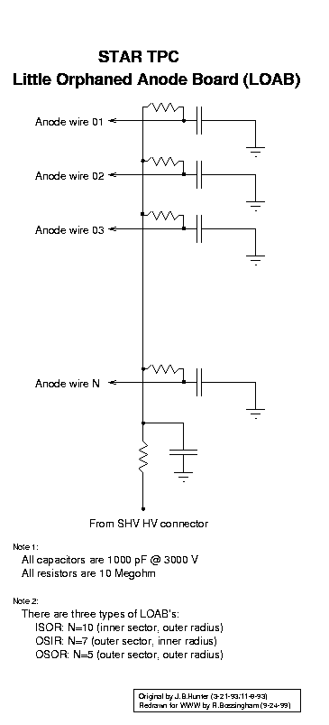
| " | 13 | 119.600 | 182 | 1.000 | " | 166 - 168 | LOAB/ISOR | |
| Outer | 14 | 127.195 | 98 | 0.764 | 1.000 | 10 - 14 | Card 9 | 2 |
| " | 15 | 129.195 | 100 | 0.583 | " | 15 - 19 | " | " |
| " | 16 | 131.195 | 102 | 0.383 | " | 20 - 24 | " | " |
| " | 17 | 133.195 | 104 | 0.210 | 0.973 | 25 - 29 | Cards 9, 10 | " |
| " | 18 | 135.195 | 106 | 0.089 | 0.894 | 30 - 34 | Card 10 | " |
| " | 19 | 137.195 | " | 0.764 | 1.000 | 35 - 39 | " | " |
| " | 20 | 139.195 | 108 | 0.582 | " | 40 - 44 | " | " |
| " | 21 | 141.195 | 110 | 0.382 | " | 45 - 49 | Cards 10, 11 | " |
| " | 22 | 143.195 | 112 | 0.210 | 0.972 | 50 - 54 | Card 11 | " |
| " | 23 | 145.195 | " | 0.893 | 1.000 | 55 - 59 | " | " |
| " | 24 | 147.195 | 114 | 0.763 | " | 60 - 64 | " | " |
| " | 25 | 149.195 | 116 | 0.582 | " | 65 - 69 | Cards 11, 12 | " |
| " | 26 | 151.195 | 118 | 0.382 | " | 70 - 74 | Card 12 | " |
| " | 27 | 153.195 | 120 | 0.209 | 0.972 | 75 - 79 | " | " |
| " | 28 | 155.195 | 122 | 0.088 | 0.893 | 80 - 84 | " | " |
| " | 29 | 157.195 | " | 0.762 | 1.000 | 85 - 89 | Cards 12, 13 | " |
| " | 30 | 159.195 | 124 | 0.581 | " | 90 - 94 | Card 13 | " |
| " | 31 | 161.195 | 126 | 0.381 | " | 95 - 99 | " | " |
| " | 32 | 163.195 | 128 | 0.209 | 0.972 | 100 - 104 | " | " |
| " | 33 | 165.195 | " | 0.893 | 1.000 | 105 - 109 | Cards 13, 14 | " |
| " | 34 | 167.195 | 130 | 0.762 | " | 110 - 114 | Card 14 | " |
| " | 35 | 169.195 | 132 | 0.580 | " | 115 - 119 | " | " |
| " | 36 | 171.195 | 134 | 0.380 | " | 120 - 124 | " | " |
| " | 37 | 173.195 | 136 | 0.208 | 0.972 | 125 - 129 | Cards 14, 15 | " |
| " | 38 | 175.195 | 138 | 0.088 | 0.892 | 130 - 134 | Card 15 | " |
| " | 39 | 177.195 | " | 0.761 | 1.000 | 135 - 139 | " | " |
| " | 40 | 179.195 | 140 | 0.579 | " | 140 - 144 | " | " |
| " | 41 | 181.195 | 142 | 0.379 | " | 145 - 149 | Cards 15, 16 | " |
| " | 42 | 183.195 | 144 | 0.208 | 0.972 | 150 - 154 | Card 16 | " |
| " | 43 | 185.195 | " | 0.892 | 1.000 | 155 - 159 | " | " |
| " | 44 | 187.195 | " | 1.000 | " | 160 - 164 | " | " |
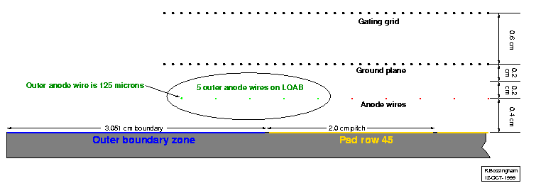
| " | 45 | 189.195 | " | " | " | 165 - 169 | Card 16, LOAB/OSOR | 2, 3 |
Notes: