Dimensions for the Field Cage & Anode & Pad Planes
The electric field cage consists of 182 rings and 183 resistors. Each ring
is separated from the next by a 2 megohm resistor. The structure of the
inner field cage and the outer field cage are identical except that the
inner field cage does not have a ground shield. Also, the location
of the pad plane is different for the inner and outer sectors.
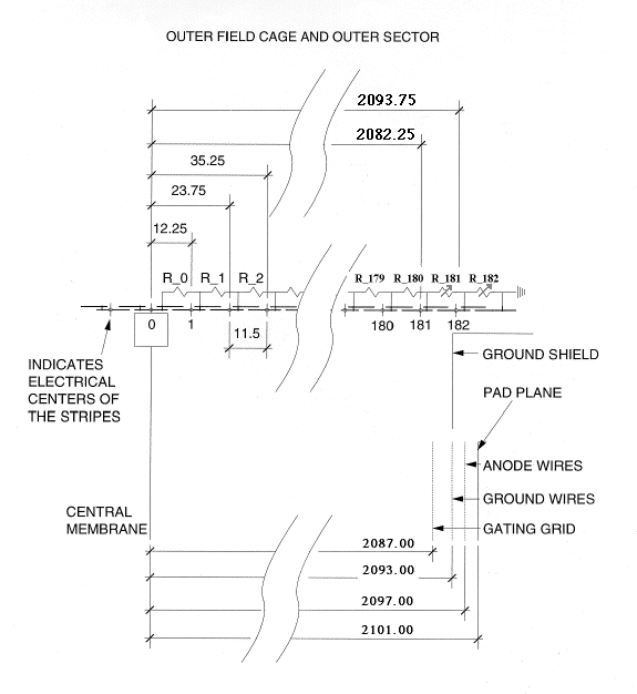
Figure from Howard Wieman, May-6-97, with dimensions updated by actual
survey by Russ Wells.
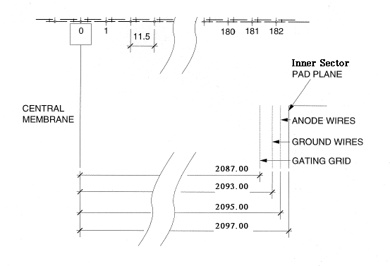
The inner sector pad plane is located at a different position than the
outer sector pad plane. However, the gating grid and ground wire
planes are aligned in the two sectors. Only the anode wire and the
pad planes are in different locations.
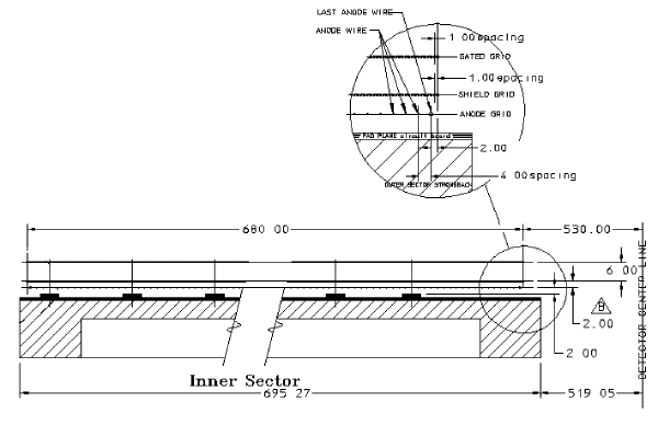
Dimensions for the inner sector are shown below. The diagram is
oriented with the beamline on the right ("Detector Center Line") as if
you were above the detector looking down on a sector in the 9 O'clock position
with the detector radius increasing to the left. For example, the
anode wires have a 4 mm spacing and the first wire at a radius of 530 mm.
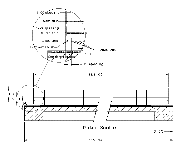
The outer sector is lies further out in radius than the inner sector.
The diagram, below, shows the outer sector in the same orientation
as the inner sector shown above. Radius increases to the left, the
phi angle goes into the page, and the outer sector starts 3 mm in radius
outside the inner sector. The gating grids and ground shield grids
have 1 mm wire spacings in both the inner and outer sectors but note that
the wire planes and pad plane are separated by different amounts in the
two sectors.
Click
here for a high resolution postscript file of these inner and outer
sector diagrams.
The anodes are 20 micron diameter gold plated tungsten wire. The
two edge wires on the anode plane are larger, 125 micron gold plated beryllium-copper,
to prevent excess gain at the boundary. Note that there are no field
wires between the anode wires. This is slightly non-traditional but
works well. The anode wires are strung with a tension of 0.50 newtons.
The ground plane and gating grids are strung with 75 micron wire
Be-Cu wire under
a tension of 1.2 newtons. The wires are Au plated.
Underneath the anode wires lie a set of readout pads. Both the
inner sector and the outer sector are shown below. The pads are 2.85
mm by 11.5 mm in the inner sector with a pad to pad spacing of 3.35 mm.
The pads in the outer sector are 6.2 mm by 19.5 mm with a spacing
of 6.7 mm.
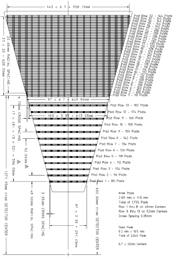
Click here for a high resolution postscript file of the pad diagram.


Page created by
Jim Thomas, send comments to
jhthomas@lbl.gov.
Last modified on March 31st, 1998

