Click on the image for a postscript file.....
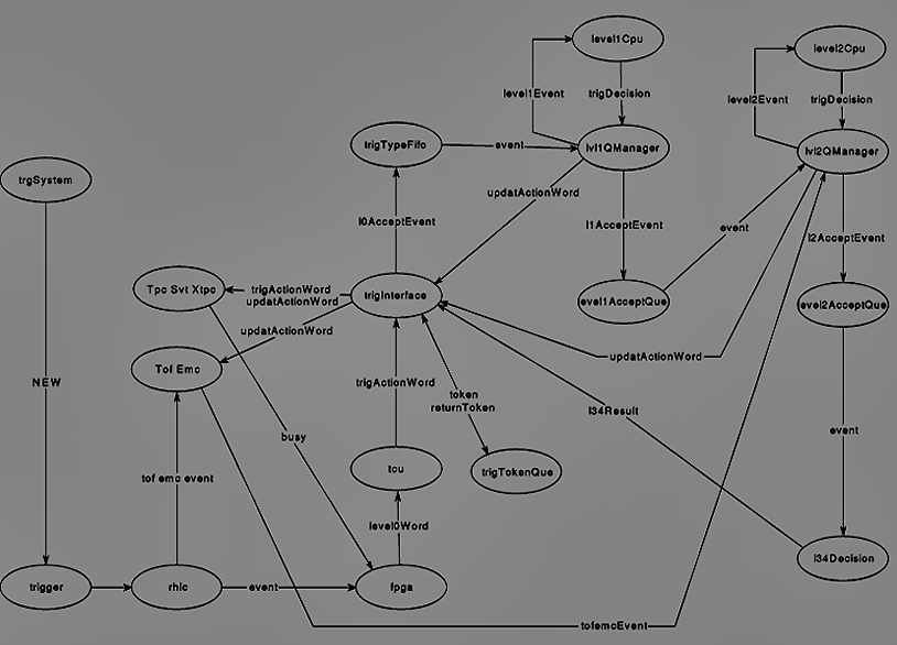
The ellipses represent objects within the model. In many instances they also correspond directly to hardware entities, those which do not include trgSystem, trigger and l34Decision. The trgSystem and trigger objects are used to instantiate or create an instance of the objects in the model. They also build the necessary connections between the objects. The l34Decision object is actually the Level2AcceptQue object described in the State Diagrams section. The name has been changed here to provide clarity to the overall action of the object. Parameters, objects etc. which are passed between the given objects are also shown.
Back to Model Description. J.P. Whitfield, Carnegie Mellon 4/20/95