Next: GEM-MSGC at HERA-B Up: Used technology Previous: Used technology Contents
The idea behind a Micro Strip Gas Counter (MSGC) [#!oed!#] is the same as that of a Multi-Wire Proportional Chamber (MWPC). Instead of wires in the MWPC an electrode structure in the MSGC is used, it is produced on a solid substrate, in case of HERA-B specific glass is used. The solid support prevents different types of instability and allows to select a small readout pitch. As a result the intended granularity and spatial resolution could be achieved.
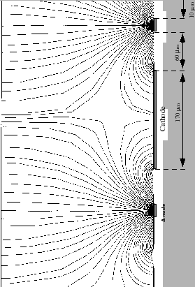
The electrode structure consists of anodes (typical width
![]() )
and cathodes (typical width
)
and cathodes (typical width
![]() ). The ground potential is applied
to the anodes and negative voltage to the cathodes (
). The ground potential is applied
to the anodes and negative voltage to the cathodes (
![]() V), they play the role
of field wires in case of the MWPC.
A drift field of several kV/cm is applied between the drift electrode and the MSGC
structure which forces electrons deposited by an ionizing
particle to drift toward the
MSGC plane. The simulated distribution of the electrical field is shown in Fig.
3.1. The amplification occurs near the anodes, where the electrical
field strength is maximum. The amplification factor can reach the order of several
thousands. The advantage of the MSGC construction is
that field cathodes are placed close to the anodes, the ions produced in the
avalanche near the anodes are quickly removed, avoiding the build-up of space
charges. A high field strength allows to speed up
drift velocity and as a result provide fast chamber signals.
V), they play the role
of field wires in case of the MWPC.
A drift field of several kV/cm is applied between the drift electrode and the MSGC
structure which forces electrons deposited by an ionizing
particle to drift toward the
MSGC plane. The simulated distribution of the electrical field is shown in Fig.
3.1. The amplification occurs near the anodes, where the electrical
field strength is maximum. The amplification factor can reach the order of several
thousands. The advantage of the MSGC construction is
that field cathodes are placed close to the anodes, the ions produced in the
avalanche near the anodes are quickly removed, avoiding the build-up of space
charges. A high field strength allows to speed up
drift velocity and as a result provide fast chamber signals.
 |
The robustness of the MSGC was tested with the help of an electron beam and photon
sources (Fe 55) [#!bspaper98!#]. The device demonstrated stable behaviour and promised
to survive during five years of operation in such environment.
In the further tests, it turned out that the electrode structure of
the detector in flux of pions and protons is destroyed nearly immediately.
The reason for such a behaviour are discharges between anodes and
cathodes, caused by heavy ionizing particles passing close to the surface
of the MSGC and depositing a large amount of charge between cathode and anode.
This phenomenon was observed for the first time during beam tests in PSI and later
reproduced in the laboratory with the help of ![]() -particle sources.
These discharges ruled out the use of the pure MSGC solution in case
of HERA-B.
-particle sources.
These discharges ruled out the use of the pure MSGC solution in case
of HERA-B.
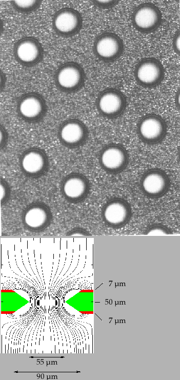
The Gas Electron Multiplier (GEM) [#!sauli!#] is a thin insulating foil, copper-clad
on both sides. The foil is perforated with a regular pattern of holes
(for the perforating a chemical etching procedure is used). The GEM is
placed in the homogeneous drift field between drift electrode and MSGC structure.
The difference of
potential between the two metal sides is ![]() 400 V. The field lines
are forced through the GEM holes and inside the holes gas amplification
can occur. The amplification depends on the geometry of the holes,
thickness of the metal-clad and field configuration above and below the GEM.
With the voltages chosen for the Inner Tracker chambers the amplification at the GEM
is in the range of 20-100.
400 V. The field lines
are forced through the GEM holes and inside the holes gas amplification
can occur. The amplification depends on the geometry of the holes,
thickness of the metal-clad and field configuration above and below the GEM.
With the voltages chosen for the Inner Tracker chambers the amplification at the GEM
is in the range of 20-100.
 |
After a variety of tests in order to overcome the MSGC discharge problems, the solution was found by using MSGC with GEM as pre-amplification structure for the ITR system, this solution has proven to be resistant enough to be used. The main advantage of this setup is that the gas amplification occurs at two well separated stages and the gas gain at the MSGC structure can be reduced. With the help of the amplification separation, the discharge probability could be reduced by several orders of magnitude and a stable and efficient operation of the GEM-MSGC can be achieved also in hadronic beams.
Yury Gorbunov 2010-10-21