Next: Infrastructure for Chamber Operation Up: The Inner Tracker System Previous: GEM-MSGC at HERA-B Contents
One GEM-MSGC chamber allows to measure one coordinate of a track impact point. In order to perform track reconstruction several chambers have to be combined, to provide measurements of the track impact points in different stereo projections.
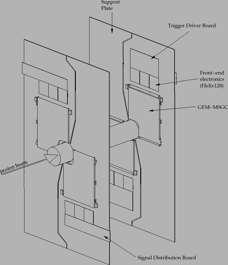
With four L-shaped detectors one plane (stereo layer) around the beam-pipe can be covered. With the aim to avoid dead regions in the acceptance the chambers are arranged in such a way that their active volumes overlap. The detectors are mounted on support plates made of carbon fibre and Nomex honeycomb (see Fig. 3.6). Several layers with different stereo angles are combined into one tracking station (superlayer).
Each superlayer consists of two separate half-stations, they cover the area
to the left and to the right of the beam-pipe (![]() ,
,![]() ). This allows to get
access to the stations for maintenance and installation. The half-stations are
mounted on the frames of the corresponding Outer Tracker stations (see Fig.
3.5).
). This allows to get
access to the stations for maintenance and installation. The half-stations are
mounted on the frames of the corresponding Outer Tracker stations (see Fig.
3.5).
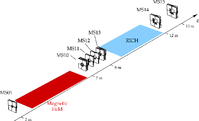
The total number of Inner Tracker chambers is 184. They are grouped according to the tasks which they have to carry out (see Fig. 3.4): magnet tracking (MC, in the magnet spectrometer), pattern recognition (PC, between magnet and RICH) and triggering (TC, chambers between RICH and ECAL). The chambers placed in the TC area are mainly needed for trigger purposes, with the aim to prolongate seeds found by the calorimeter and muon pretrigger system into the main tracking system (PC, MC).
During the comissioning run in 1999/2000, 136 chambers were installed and routinely operated in the Inner Tracker system, missing were the TC chambers. During the shutdown in 2000-2001, the decision was made to remove the chambers inside the magnet region in order to improve the resolution of the ECAL. Therefore, in the running period 2002, 149 chambers were installed and operated, in the TC area only half (24 chambers) of the installed chambers were read-out.
In order to identify each chamber, the following naming convention was
used. The first two numbers identify the superlayer (01, ... 15).
The third and fourth character are a +- (x) and (y) indicating the position
in the ![]() and
and ![]() direction respectively. The last digit indicates the position
inside the superlayer. For example MS10+-3 is the third layer
in station MS10, in the quadrant covering positive
direction respectively. The last digit indicates the position
inside the superlayer. For example MS10+-3 is the third layer
in station MS10, in the quadrant covering positive ![]() and negative
and negative ![]() .
.
The information summarizing the setup 2002 can be found in Tab. 3.2.
 |
 |
|
 |