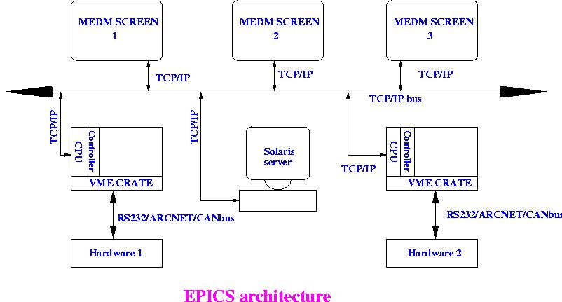
The Operator needs a terminal through which he/she connects to the central solaris server where the Database and the code is kept. This connection would be through a simple TCP/IP (Ethernet) connection. The CPU is connected to computer (PC or workstation) through serial port. The operator needs to log in to this computer and talk to the CPU. The CPU is on TCP/IP bus so that it reads the startup script from the central server when it boots and starts executing the code. The address of the central server is specified in the boot prompt. In the mean time the operator opens the GUI window on his/her terminal and ready to talk to hardware through the code.
From the disscussion so far we have come to know that the system essentially has three steps:
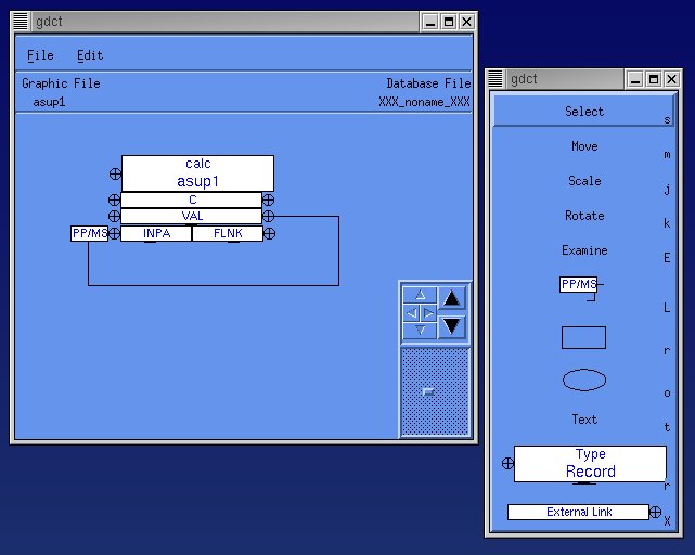
There is a tool called Graphical Database Configuration Tool (GDCT) which allows the user to build the database and visualize various links between records and process variables. One can create the variables, set different precission, set alarm limits and many more things through the tool. Once saved it creates a .db file which is nothing but a text file. The figure below shows a typical GDCT window.
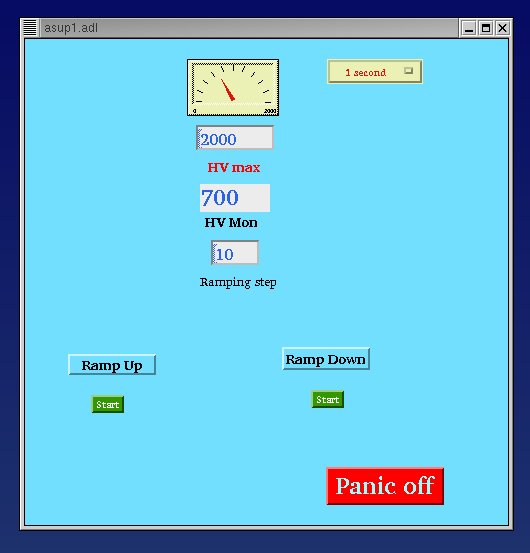
Similarly there is another tool called Motif Editor and Display Manager (MEDM) which is used to create the GUI window. There are various objects like monitors, controllers and simple graphical objects like arc, line, oval or text. These objects takes different variables from the Dbase as there control channels. So the operator can monitor the values of various Dbase variables and just by a click of mouse on the object the operator can access the Dbase variable and modify them if needed. The file is saved as a .adl file which is again a text file. The figure below shows a typical GUI window created by MEDM.
The third and crucial step is writing the code. The code is written in C language. There are two ways to write a code. One is to write a C code which does not need any explanation. The other way to write the sequencer code is a two step process. First is to write the code in State Notation Language (SNL) and then convert that to a C code by using a State Notation Compiler (SNC). The SNL code is written with an extention ".st". SNL is a simple but powerful tool to program sequential operatons in a real time operating system. This is based on the concept of the State Transision Diagram (STD) which is nothing but a graphical notation to specify the behaviour of a control system in terms of control transformations.
The figure below shows a simple example of a STD. Here the level of an input voltage is sensed, and a light is turned on if the voltage is greater than 5 volts and turned off if the voltage becomes less than 3 volts. Note that the output or action depends not only on the input condition, but also on the current memory or state. For instance, specifying an input of 4.2 volts does not directly specify the output, but depends on the current state.
The SNL code for the above example is :
******************************************
   program level_check
   float  v;
   assign  v to "Input_voltage";
   monitor  v;
   short  light;
   assign  light to "Indicator_light";
   ss volt_check {
     state light_off
     {
       when (v > 5.0) {
         /* turn light on */
         light = TRUE;
         pvPut(light);
       } state light_on
     }
     state light_on
     {     when (v < 5.0) {
         /* turn light off */
         light = FALSE;
         pvPut(light);
       } state light_off
     }

******************************************
It is to be noticed that the SNL appears to have a structure and syntax similar to those of C language. In fact SNL uses its own syntax plus subset of C, such as expressions, assignment statements and function calls. In this example there are two blocks defining two states light_off and light_on. The pvPut function puts or writes the value of variable "light" to the appropriate Dbase channel "Indicator_light" assigned to it. The actions inside the two states are executed depending upon the value of the monitor "v".
The above code converted to C language