|
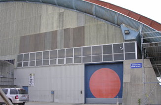
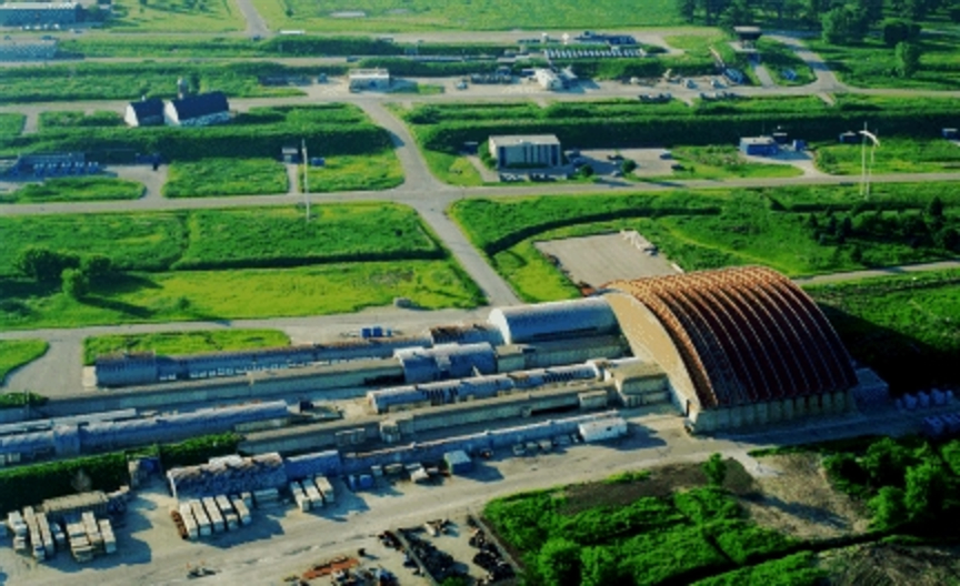
T963 Details: T963 program which takes the advantage of Meson Test-Beam Facility at FNAL is located in MT6, see Fig 1&2. The facility can provide charged particle beam such as Muon, Pion and Proton from 1GeV to 120GeV.
A layout of the Meson Lab, MTest beamline elements and MTest user areas can be found : More detail on the facility recommended see
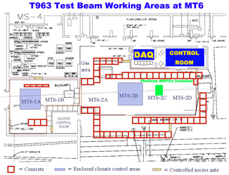
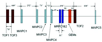
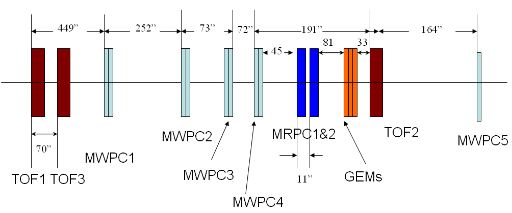
here. T963 Detectors Layout: Fig 3 displays a detailed drawing where T963 is located in the main experiment hall. The blue area shows where the DAQ room and control room are. The green colored area points out where the motive platform is. It is used to support two Large Area MRPCs and makes it easily to perform spacial resolution scan. T963 detectors layout can be found in Fig 4, it shows the geometrical distribution of two TOF scintillators, nine MWPC wire chambers, two MRPC chambers and three GEM chambers along the beam line.
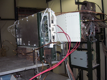
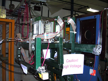
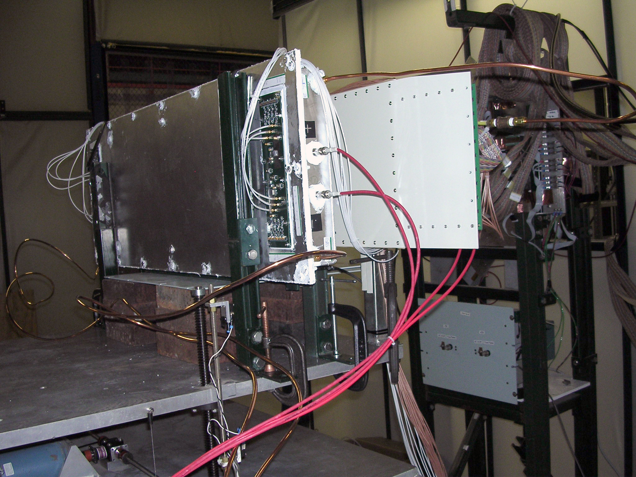
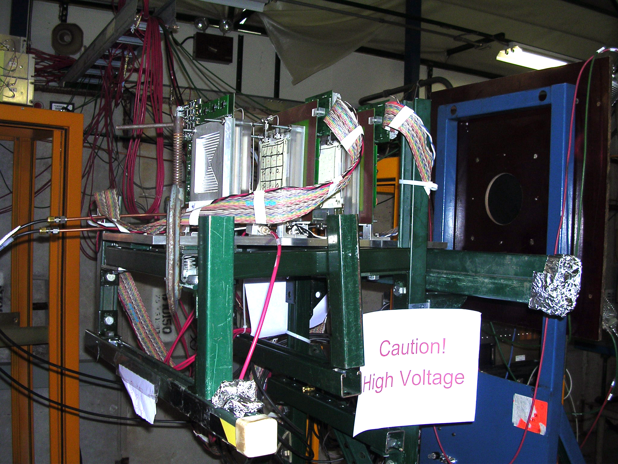
Module Definition: Modules are defined as MODULE #1 (built at Tsinghua Univ., white tray box) and MODULE #2 (built at USTC, silver tray box) along the beam insert direction. Installation Details: From April 26th, detector installations has begun in the MT6 areas. Fig 5 shows that the MRPCs were installed on the movable platform and began to flow gas. The photograph was taken from the High Voltage side. Due to MODULE #2 has a thicker try box than MODULE #2, it was installed behind the latter along the beam line direction. In Fig 6, three GEMs were fixed between MRPC modules and TOF2 towards north. Both the pictures were taken just when GEMs high voltage was applied on April 30th, 2007.
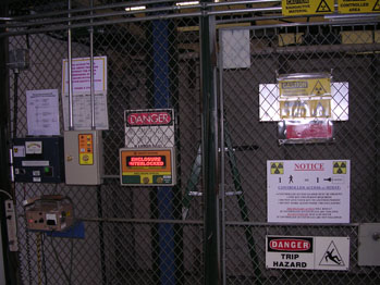
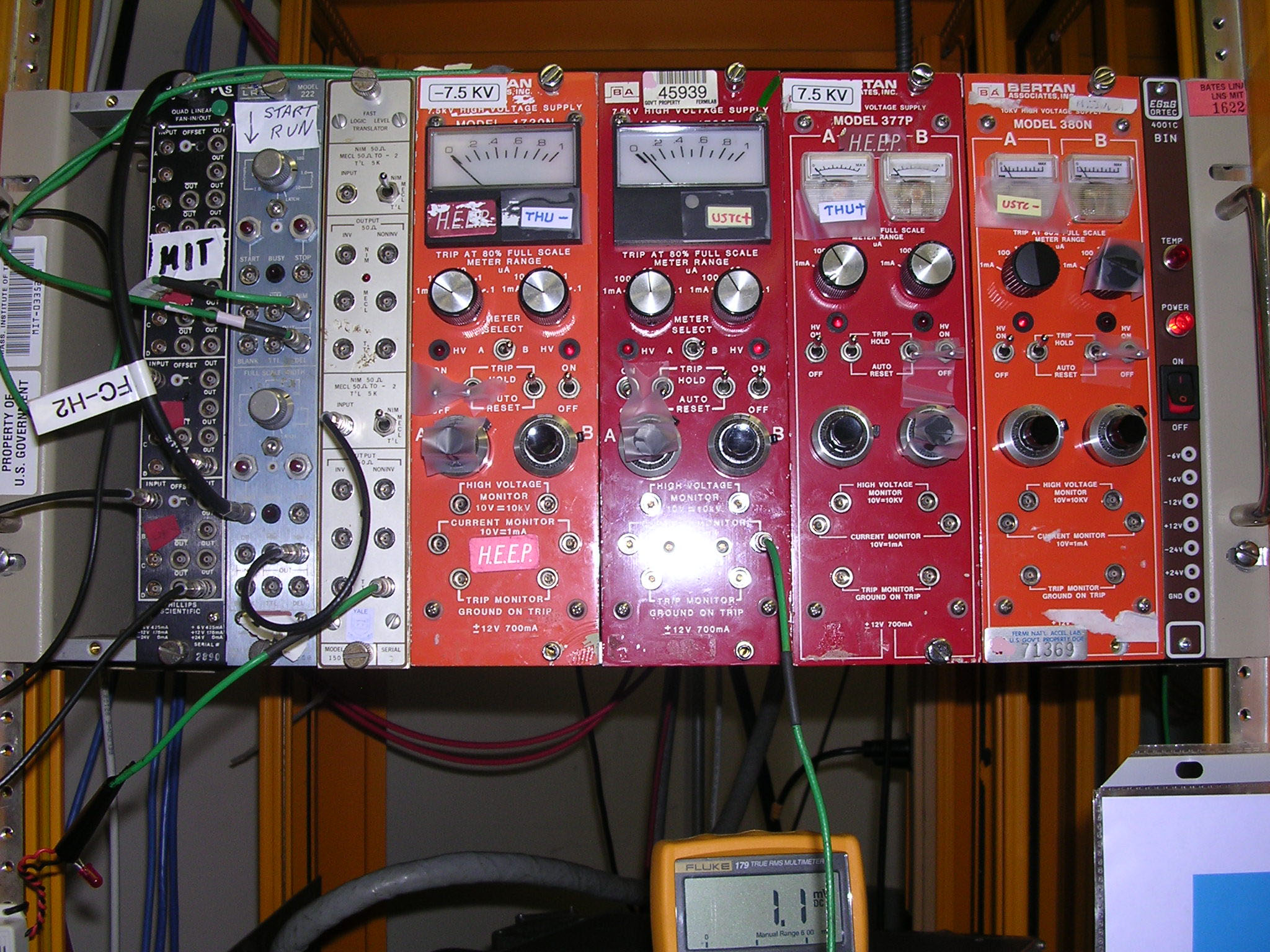
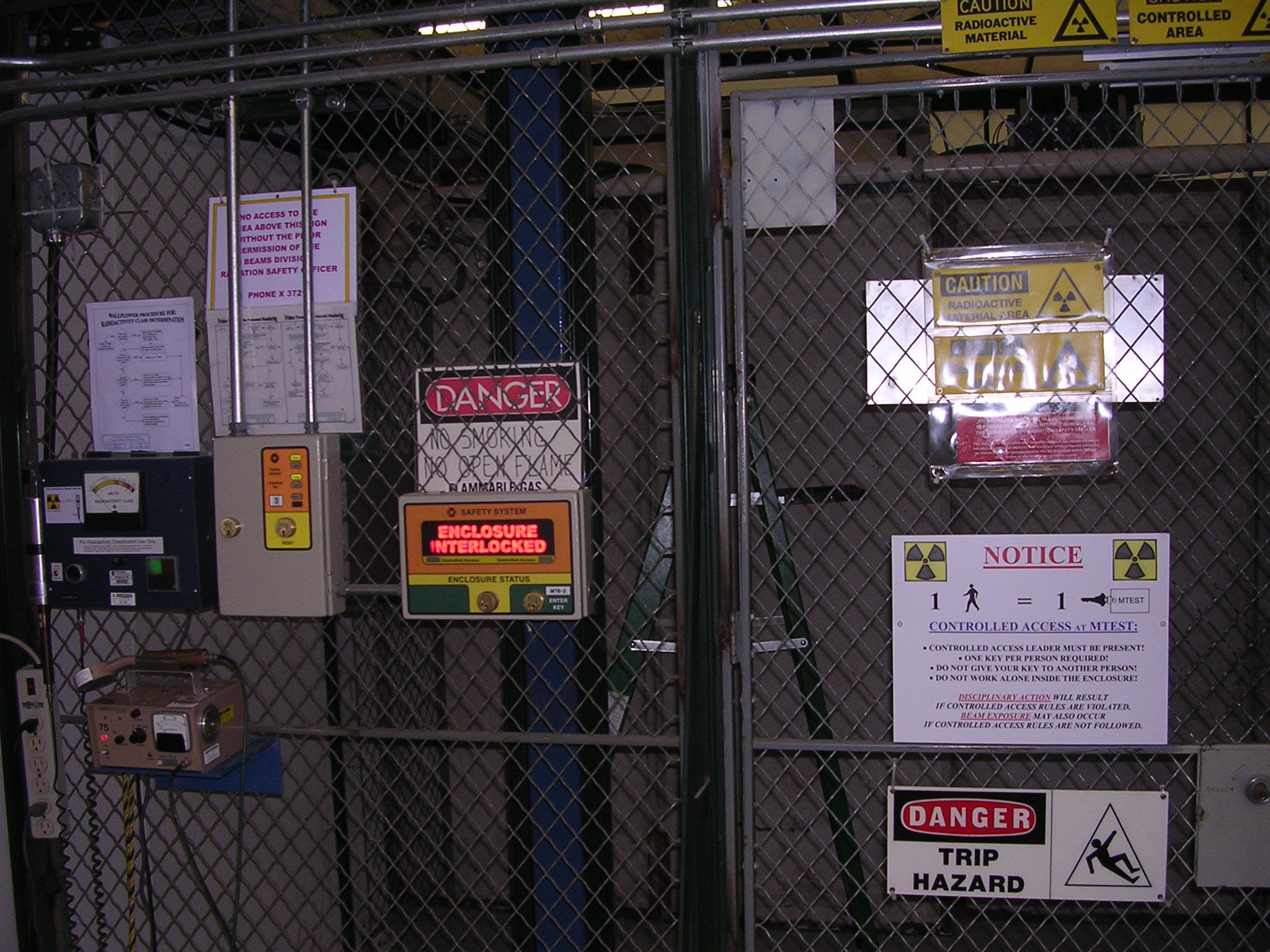
Beam running: High voltage is applied to MODULE #1 7,300V and MODULE #2 6,300V. Table 1 shows that #2 has a higher high voltage dark current than #1, for both cathode and anode. We estimated that compared with #1, #2 relatively had a lower resistance and weaker static electric field generated by collecting ionized electron and ion pairs. The maxim values in the table were recoded when the detectors were working on the beam spills, while minimum were stable and in the same value as dumping. Fig 7 shows HV crate is under the working status. In Fig 8, it shows the experimental areas were isolated when beam is running.
|
||||||||||||||||||||||||||||||||||||||||||||||||||||||||||||||||||||

