The Electric Drift
Field for the STAR TPC
When a charged particle traverses the TPC volume,
it ionizes gas atoms every few tenths of a millimeter along its
path and leaves behind a cluster of electrons. The electron
clusters then drift to the anode plane under the influence of an
externally applied electric field where their time of arrival and
location is recorded.
An animated simulation of the drift
is available here.

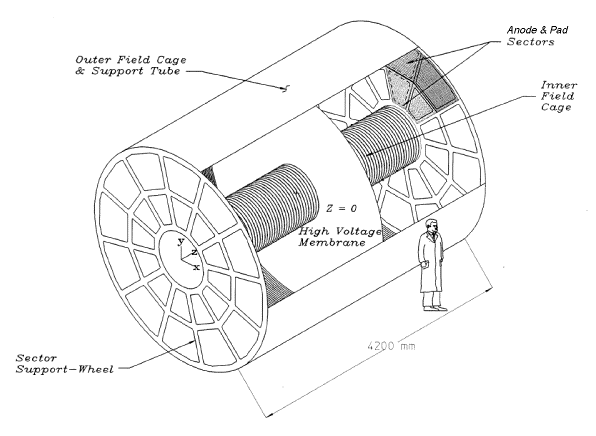
In the STAR TPC, the electric field is provided by the outer
field cage (OFC), the inner field cage (IFC), and the high
voltage central membrane (CM). The purpose of the OFC and
IFC is to provide a nearly perfect electric field in which to
drift the electrons to the anode plane since any distortions in
the field will result in a distortion of the recorded
tracks. The OFC and the IFC also serve to define the active
gas volume and were designed to contain the TPC gas and prevent
it from being contaminated with outside air. The central
membrane is located in the middle of the TPC and is held at high
voltage. The anode and pad planes are organized into
sectors on each end of the TPC and the pads are held at ground
potential. The OFC and IFC include a series of
gradient rings that divide the space between the central membrane
and the anode planes. The total distance from the CM to
either anode plane is slightly greater than 2 meters. There is
approximately one ring per centimeter and the rings are biased by
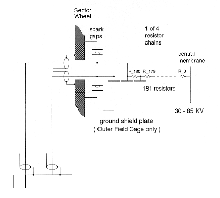
a chain of resistors that connect to the CM, the anode plane
ground, and each of the gradient rings inbetween. The rings
are separated by two-megohm resistors and there are 182 rings and
183 resistors in each chain.

The last two resistors are adjustable and are housed in a rack
which is external to the TPC. Note that the outer field
cage has a "ground shield" attached to ring 182.
It marks the end of the TPC drift volume and is used to better
define the shape of the field at the terminus. The
inner field cage does not have a "ground
shield". The spark gaps are safety devices for
the protection of personnel and equipment in case the external
resistors are disconnected while the field cages are biased.
There are four resistor chains. One for
each end of the two field cages. Thus, IFC East, IFC West,
OFC East, and OFC West.


Page created by Jim
Thomas, send comments to jhthomas@lbl.gov.
Last modified on March 31st, 1998