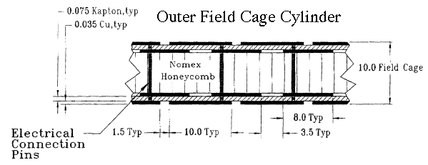
The field cages are designed to be low mass and "thin" for particles
passing through them yet they must also be gas tight and strong enough
to be self supporting. So the field cages were built using two sheets
of metal coated Kapton separated by a honeycomb of Nomex. The whole
assembly was rolled into a tube and the sheets of Kapton were epoxied to
the honeycomb to form a strong sandwich of material.

The Kapton in the outer field cage (OFC) is laminated with a 35 micron
layer of copper and the metal layer is etched into stripes so that, after
rolling the tube, the stripes become rings around the tube.
| Width of the rings | 10.0 mm |
| Width of the gap between rings | 1.5 mm |
| Pitch of the stripe pattern (ring to ring) | 11.5 mm |
| Number of rings | 182 |
| Structure | Material | cm | g/cm**3 | Rad Length g/cm**2 | g/cm**2 | Rad Length % |
| Insulating gas | N2 | 30.00 | 0.001 | 37.99 | 0.038 | 0.10 |
| TPC IFC | Aluminum | 0.004 | 2.700 | 24.01 | 0.010 | 0.04 |
| TPC IFC | Kapton | 0.015 | 1.420 | 40.30 | 0.022 | 0.05 |
| TPC IFC | Nomex | 1.27 | 0.064 | 40 | 0.081 | 0.20 |
| TPC IFC | Adhesive* | 0.08 | 1.20 | 40 | 0.091 | 0.23 |
| IFC Total (w/gas) | 0.62 |
| Structure | Material | cm | g/cm**3 | Rad Length g/cm**2 | g/cm**2 | Rad Length % |
| TPC gas | P10 | 150.00 | 1.56e-03 | 20.04 | 0.234 | 1.17 |
| TPC OFC | Copper | 0.013 | 8.96 | 12.86 | 0.116 | 0.91 |
| TPC OFC | Kapton | 0.015 | 1.420 | 40.30 | 0.022 | 0.05 |
| TPC OFC | Nomex | 0.953 | 0.064 | 40 | 0.061 | 0.15 |
| TPC OFC | Adhesive* | 0.05 | 1.20 | 40 | 0.060 | 0.15 |
| OFC Total (w/gas) | 2.43 |
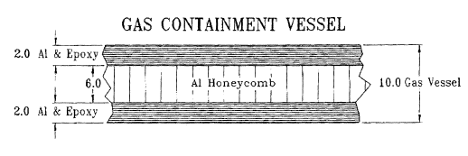
The outer field cage is nested inside an aluminum gas containment vessel
which presents additional radiation lengths of material to particles passing
out of the TPC in the radial direction. It is separated from
the OFC by 5.7 centimeters of nitrogen gas. The gas vessel also has
aluminum brackets glued onto its outer circumference to support the CTB
trays and to temperature stabilize the TPC.

| Structure | Material | cm | g/cm**3 | Rad Length g/cm**2 | g/cm**2 | Rad Length % |
| Insulating gas | N2 | 5.70 | 0.001 | 37.99 | 0.007 | 0.02 |
| Gas Vessel | Aluminum | 0.40 | 2.590 | 24.01 | 1.036 | 4.31 |
| Gas Vessel | Honeycomb | 0.60 | 0.037 | 24.01 | 0.022 | 0.09 |
| Gas Vessel | Al Brackets | 0.635 | 2.590 | 24.01 | 1.645 | 6.85 |
| Gas Vessel | Adhesive* | 0.157 | 1.20 | 40 | 0.189 | 0.47 |
| Gas Vessel Total | 11.74 |
Finally, you might also want to consider the beam pipe, the SVT, and the CTB trays if you are interested in the total radiation length budget between the vertex and some part of the detector. The beam pipe is approximately 1 mm of beryllium which is equivalent to 0.28% radiation lengths. And the SVT is roughly 1.5% radiation lengths without the fourth layer.