See the TPC wire plane diagram
(Postscript) for the wire layout; or the
calculated capacitances
for the anode, ground and gating-grid wire capacitances. Note that
there is also some "lumped" capacitance due to the
wire terminations.
HV is fed to the TPC anode wires from either an
"Anode Bias Distribution Board" (ABDB)
in groups of 20, or from a
"Little Orphaned Anode Board" (LOAB,
sometimes also referred to as a "Little Orphan Annie Board") in smaller groups.
There are three distinct types of LOAB:
- "Inner Sector, Outer Radius" (ISOR)
- "Outer Sector, Inner Radius" (OSIR)
- "Outer Sector, Outer Radius" (OSOR).
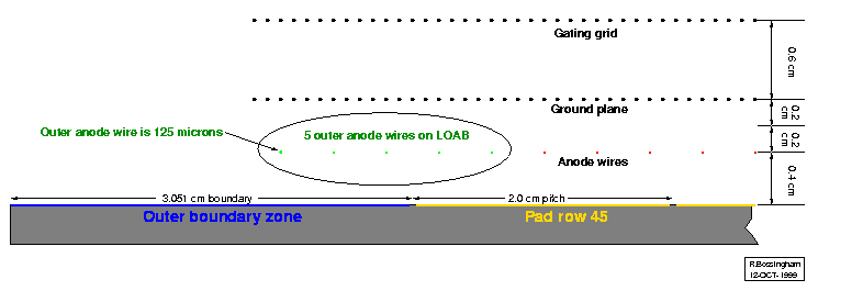
The pad plane geometry in the region of the OSOR anode wires
is shown here as an example:

Within each subsector, 160 anode wires connect to ABDB's; the signals
go to 16 MWC card sockets on each sector.
(Two subsectors per sector, with 160 instrumented wires/subsector and
20 channels/MWC socket, works out to 16 sockets/sector.)
Special MWC boards - resembling the
FEE cards for the pads - can plug into these sockets. For the
engineering run in late 1999, Sockets #2-16 held unpowered MWC cards,
while, at this point, Socket #1 will only hold a grounding card. It
is expected that Socket #1 will eventually be fitted with a modified
MWC board. Therefore, one expects
gain calibration bias
when comparing different pad rows with the ground-wire pulser.
Finally, a dedicated MWC readout board -
resembling the main RDO boards for the pads - in mounted on each
sector to aquire and transmit data from as many as 16 MWC cards.
Inner sector anode-wire information and MWC-socket connections:
| Wire range |
Radius to
first wire
(cm) |
Radius to
last wire
(cm) |
ABDB |
LOAB |
MWC
socket |
Notes |
| 1 - 20 |
53.200 |
60.800 |
X |
|
1 |
1, 2 |
| 21 - 40 |
61.200 |
68.800 |
X |
|
2 |
|
| 41 - 60 |
69.200 |
76.800 |
X |
|
3 |
|
| 61 - 80 |
77.200 |
84.800 |
X |
|
4 |
|
| 81 - 100 |
85.200 |
92.800 |
X |
|
5 |
|
| 101 - 120 |
93.200 |
100.800 |
X |
|
6 |
|
| 121 - 140 |
101.200 |
108.800 |
X |
|
7 |
|
| 141 - 160 |
109.200 |
116.800 |
X |
|
8 |
|
| 161 - 170 |
117.200 |
120.800 |
|
ISOR |
|
1 |
Outer sector anode-wire information and MWC-socket connections:
| Wire range |
Radius to
first wire
(cm) |
Radius to
last wire
(cm) |
ABDB |
LOAB |
MWC
socket |
Notes |
| 1 - 7 |
122.795 |
125.195 |
|
OSIR |
|
3 |
| 8 - 27 |
125.595 |
133.195 |
X |
|
9 |
|
| 28 - 47 |
133.595 |
141.195 |
X |
|
10 |
|
| 48 - 67 |
141.595 |
149.195 |
X |
|
11 |
|
| 68 - 87 |
149.595 |
157.195 |
X |
|
12 |
|
| 88 - 107 |
157.595 |
165.195 |
X |
|
13 |
|
| 108 - 127 |
165.595 |
173.195 |
X |
|
14 |
|
| 128-147 |
173.595 |
181.195 |
X |
|
15 |
|
| 148 - 167 |
181.595 |
189.195 |
X |
|
16 |
|
| 168 - 172 |
189.595 |
191.195 |
|
OSOR |
|
3 |
Notes:
-
Inner sector Wires 1 (R=53.20 cm) and 170 (R=120.80 cm) have
125-um (rather than 20-um) diameter; their gain is very low.
-
MWC socket 1 was unfilled during Summer 1999 running. In Fall 1999,
a grounding card (modified FEE grounding card) will be installed, but
it is hoped that the socket will be instrumented eventually.
-
Outer sector Wires 1 (R=122.795 cm) and 172 (R=125.195 cm) have 125-um
(rather than 20-um) diameter; their gain is very low.
-
MWC's were not powered until Spring 2000 running, so the
input impedance was not well-defined
before then; the inputs were, effectively, partway between floating
and ground.
-
All ABDB and LOAB resistors are 10 megohm; all capacitors are 0.001
uF. HV goes through a resistor to the group of 20 anode wires, then
through another resistor to each anode wire. Anode is AC coupled
through a capacitor.
-
On ABDB's, a connection to the MWC socket and a resistor follows the
capacitor; on LOAB's, the capactor connects directly to ground.
-
See ABDB and LOAB
figures for more information.
-
Through September 1999, the positions of the MWC wires in the
GSTAR Monte Carlo were slightly offset radially. The offset
was +1.669 cm in the inner subsector and +0.093 cm
in the outer subsector.
Thanks to Jim Hunter, Eric Hjort and Jon Wirth for information and
prints on the ABDB's, LOAB's and their connections; and to Spencer
Klein and Joakim Nystrand for information on the MWC cards.

