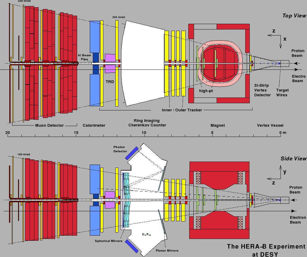
Next: The Inner Tracker System Up: The HERA-B experiment Previous: Detector overview Contents
The experiment was foreseen to collect ![]() -decays in the channel
-decays in the channel
![]() (
(
![]() and
and
![]() ) which are just a tiny
fraction of the overall number of events. The cross section for
) which are just a tiny
fraction of the overall number of events. The cross section for
![]() is in the range of 7-70 nb/nucleon while the total inelastic cross
section for proton-nucleon scattering is of the order of 13 mb/nucleon.
The branching ratio of
is in the range of 7-70 nb/nucleon while the total inelastic cross
section for proton-nucleon scattering is of the order of 13 mb/nucleon.
The branching ratio of
![]() is
is ![]() 12% and for
12% and for
![]() is approximately 68%. One
is approximately 68%. One
![]() is expected to be produced per
is expected to be produced per ![]() inelastic events. Therefore, it is not possible to read out and record
each event, with in total 600.000 readout channels and an interaction rate of about
10 MHz this would mean 6 Tbit/s. This is why a highly selective trigger is needed.
inelastic events. Therefore, it is not possible to read out and record
each event, with in total 600.000 readout channels and an interaction rate of about
10 MHz this would mean 6 Tbit/s. This is why a highly selective trigger is needed.
HERA-![]() uses a multi stage trigger with a rejection factor of about
uses a multi stage trigger with a rejection factor of about
![]() [#!balag!#].
[#!balag!#].
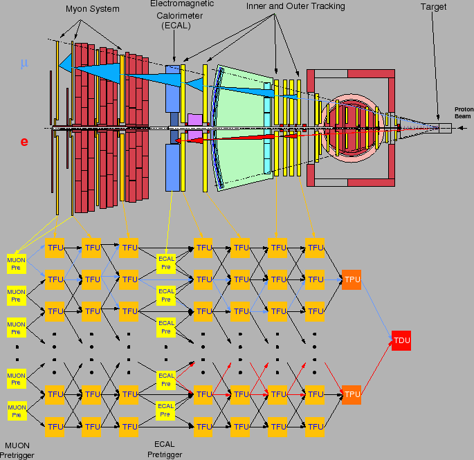
Pretriggers. The information about possible track candidates are provided
by pretriggers implemented in three sub-detectors: ECAL, muon and high-pt.
First Level Trigger. The first level trigger (FLT) is a hardware trigger
which uses a discrete track following algorithm for track tracing. The algorithm
starts from the seeds provided by the pretriggers (Muon and ECAL) and extrapolates
backwards so called Regions of Interest (RoI) to the tracking superlayers,
using as an assumption
that the tracks originate from the target. If the algorithm finds a hit in a
layer of the tracking station, the track information is updated and the search for
coincident hits in the next layer in a smaller region of interest is performed.
Fig. 2.4 shows the FLT algorithm schematically.
If the FLT succeeds to trace both tracks to the exit of the magnet spectrometer, the Track Parameter Unit (TPU) estimates the momenta of the tracks. For each pair of tracks an invariant mass is calculated, if the obtained mass exceeds a threshold the event is kept and otherwise rejected. In order to suppress the amount of data which has to be transfered from the readout electronics to the FLT, only four superlayers of the tracking system are used. The maximum possible FLT output rate of the triggering setup is about 50 kHz.
Second Level Trigger. Next trigger step is the Second Level Trigger (SLT),
implemented as a software trigger and based on a farm of 240 standard PCs. If an
event is accepted by the FLT, all event information which is stored in the
front-end electronics is transfered to the Second
Level Buffer (SLB). Each triggered event is taken by one node of
the SLT farm for processing. The algorithm starts from RoIs defined by
the FLT and refines the track parameters using additional information about
drift time of OTR and full resolution of the Inner Tracker. Finally, tracks
which are reconstructed in the Main Tracker are propogated through the spectrometer
magnet and track segments are reconstructed in the Vertex Detector. The event is accepted,
if the trigger tracks can be matched with a VDS track segment and both tracks form a
vertex. Complete information about the accepted event is than transmitted to the SLT
node which forms the complete event record and transfers the record to the
Fourth Level Trigger.
Fourth Level Trigger. The Fourth Level Trigger farm consists of 200 CPUs.
At this stage a complete reconstruction of an event is performed with best
knowledge about calibration and alignment constants. In parallel the search for
interesting physical processes is performed, events with candidates are marked
for fast offline access during the analysis.
At the end, raw detector information and output of the reconstruction program are stored in one record and archived on tape in the DESY computing center. The output rate at the end of the Fourth Level Trigger is limited to about 30 events per second.
Trigger Performance in 2002/2003.
The above described trigger scenario suffered from the low efficiencies
of the tracking stations and dead regions. Therefore a special trigger
mode was used for data taking 2002/03, called the FLT/SLT ``Star Mode''.
Instead of two lepton track requirement in the FLT, only a single track
is required. The SLT algorithm is started from the two pretrigger candidates.
With this scenario a rate of more than 1000 ![]() per hour has been achieved
and approximately 250.000
per hour has been achieved
and approximately 250.000 ![]() s decaying in electron and muon channels have been
collected.
s decaying in electron and muon channels have been
collected.
Yury Gorbunov 2010-10-21