Next: Trigger Up: The HERA-B experiment Previous: The HERA Storage ring Contents
The HERA-B coordinate system originates at the target
system with the ![]() axis directed along the proton beam, the
axis directed along the proton beam, the ![]() axis pointing upward and the
axis pointing upward and the ![]() axis pointing to the center of the HERA ring.
axis pointing to the center of the HERA ring.
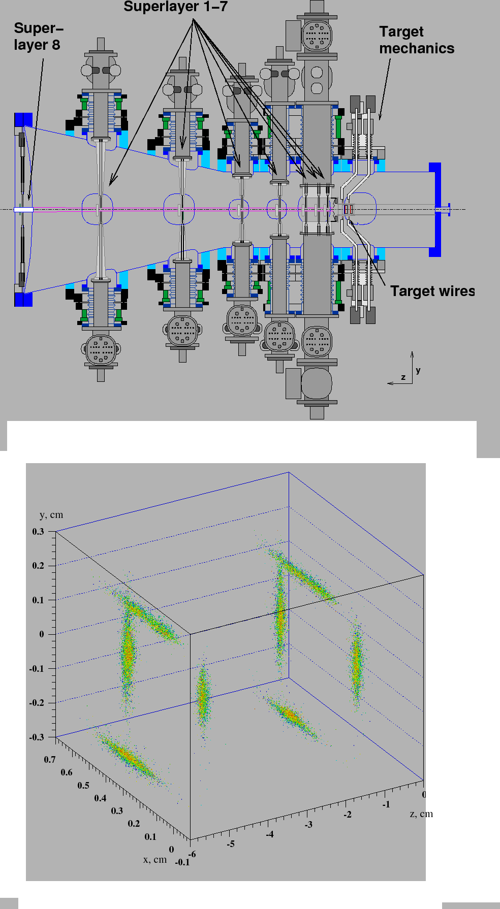
Target. The target consists of two stations with four wires each [#!SelI!#].
They can be steered individually which allow to select specific
wire configurations. Wires inserted into the proton beam halo follow
movements of the beam, keeping the interaction rate approximately constant.
The interaction rate is measured by a set of scintillator hodoscopes placed at the exit window of the RICH vessel. In case of a multi-wire configuration the individual contribution of each wire to the overall rate can be measured with the help of charge integrators.
During running in 2000, the first target station was equipped with titanium wires and the second station contained wires made out of aluminium, carbon and tungsten. During data taking in 2002 - 2003 aluminium, carbon, tungsten and titanium wires were used with slightly different setup. The use of different wires allows to measure nuclear effects in particle production. These measurements can be performed using two wires at the same time, reducing possible impact of the detector or beam changes with time on the systematic error.
The target mechanics and the Vertex Detector System are build into one vacuum vessel which is a part of the primary vacuum of the proton beam (Roman Pot system).
The original reason for the target setup of 8 wires subdivided to 2 stations was chosen to achieve efficient primary vertex reconstruction at an operation rate of about 40 MHz leading to multiple interactions in one bunch crossing.
Vertex Detector System. The Vertex Detector System [#!braeuer!#]
has eight superlayers build of 64 double-sided silicon micro-strip counters. The
first eight superlayers of the VDS are placed inside the vacuum vessel.
In order to retract the counters during the beam injection the system
of manipulators and Roman pots to reduce multiple scattering is foreseen.
In the operation phase (the
beam reached stable conditions) the counters are moved into their
nominal positions, about 10 mm away from the beam core.
 |
The detector has a readout pitch of 50 ![]() m and can measure tracks
with polar angles from 10 till 250 mrad.
The track information provided by the VDS is used to reconstruct
primary and secondary vertices from direct decays like
m and can measure tracks
with polar angles from 10 till 250 mrad.
The track information provided by the VDS is used to reconstruct
primary and secondary vertices from direct decays like
![]() or
or
![]() . A resolution for secondary
vertices of about 70
. A resolution for secondary
vertices of about 70 ![]() m in the
m in the ![]() plane perpendicular to the beam
direction and 500 - 700
plane perpendicular to the beam
direction and 500 - 700 ![]() m along the beam direction were obtained with real data.
m along the beam direction were obtained with real data.
Spectrometer Magnet. A warm dipole magnet, with a
magnetic field integral of 2.2 Tm is used for momentum analysis. The magnetic
field is orientated along the ![]() axis.
axis.
The deflection of the proton beam by the spectrometer magnet is compensated by three additional magnets placed upstream of the experiment. The electron beam passes through the spectrometer magnet as well, it is protected by a specifically shaped pole face of the spectrometer magnet and by a set of cylinders around the electron beam pipe.
Main Tracking System. The stations of the tracking system are situated
along the beam pipe. In order to be able to achieve the required spatial resolution
and to cope with the partical fluxes, the system is divided into two parts: the Inner
and Outer Tracker. The Inner Tracker (ITR) uses the GEM-MSGC technology and has
to withstand a high particle flux of up to
![]() . It covers the
region from 5 to 30 cm from the beam-pipe and provides a spatial resolution
of about 100
. It covers the
region from 5 to 30 cm from the beam-pipe and provides a spatial resolution
of about 100 ![]() m. The ITR is described in detail in Chapter 3.
m. The ITR is described in detail in Chapter 3.
The Outer Tracker (OTR) [#!OTR!#] covers an area starting at 20 cm to 300 cm around
the beam-pipe with a small overlap to the ITR. It is built of honeycomb drift
chambers with a cell size of 5mm in the inner region and 10mm in the outer region.
In both tracking systems, chambers are arranged into layers covering a full plane
in the ![]() plane and several layers are grouped into one superlayer. The layers of
one superlayer are arranged in three different wire orientations of:
plane and several layers are grouped into one superlayer. The layers of
one superlayer are arranged in three different wire orientations of:
![]() with
respect to
with
respect to ![]() axis. The
stereo chambers are needed in order to resolve the
axis. The
stereo chambers are needed in order to resolve the ![]() coordinate. The hit resolution
of the OTR is about 350
coordinate. The hit resolution
of the OTR is about 350 ![]() m.
m.
Ring Imaging Cerenkov Counter. The Ring Imaging Cerenkov Counter [#!Arin!#]
is used to distinguish between different particle types. The detection is based on
the principle that charged particles passing with a speed exceeding that of light
through a medium emit photons.
The HERA-![]() RICH is filled with perfluoro-butane (
RICH is filled with perfluoro-butane (
![]() ) at ambient
pressure. To register emitted Cerenkov light an array of photomultiplier
tubes is used. With such a kind of gas the Cerenkov momentum threshold is 2.6 GeV
for pions, 9.0 GeV for kaons and 17.2 GeV for protons.
) at ambient
pressure. To register emitted Cerenkov light an array of photomultiplier
tubes is used. With such a kind of gas the Cerenkov momentum threshold is 2.6 GeV
for pions, 9.0 GeV for kaons and 17.2 GeV for protons.
The Cerenkov light emitted by one particle forms a ring at the plane of photomultipliers.
If a ring is found and matched with a track, the particle identification program can assign a likelihood to each particle type according to the track momentum and the ring radius.
Electromagnetic Calorimeter.
The Electromagnetic Calorimeter (ECAL) [#!Avon!#] is a sampling calorimeter of
``shashlik'' type: each cell consists of a combination of scintilliator plastic
planes and absorbers. Wave-length shifting fibers are inserted in the absorbing
and scintillating material. The light output of the optical fibres is collected by
photomultipliers. The ECAL is subdivided into inner, middle and outer parts with
cell sizes of 2.23x2.23 ![]() , 5.58x5.58
, 5.58x5.58 ![]() and 11.15x11.5
and 11.15x11.5 ![]() respectively.
In the inner part of the ECAL a tungsten alloy as absorber is used while outer
and middle parts use lead. The radiation length of the calorimeter is about 20 - 22
radiation length
respectively.
In the inner part of the ECAL a tungsten alloy as absorber is used while outer
and middle parts use lead. The radiation length of the calorimeter is about 20 - 22
radiation length ![]() .
.
The calorimeter is designed to measure the energy of the electrons and photons and to distinguish them from hadrons. In addition the ECAL is used in the trigger scheme to provide a pretrigger.
Muon system. [#!Eiges!#] To identify muons, a system of tracking
chambers is placed behind the ECAL. In order to suppress background from
hadrons, steel and concrete absorbers are
placed in front of these stations. In total the absorber has a thickness of about
20 interaction lengths. The inner part of the Muon system is made of Gas Pixel
Chambers with a cell size of 9x9 ![]() . They cover an area from 14 cm to 40 cm
around the beam-pipe.
. They cover an area from 14 cm to 40 cm
around the beam-pipe.
The first two stations of the Muon System in the outer part consist of proportional
wire chambers arranged in three stereo views (
![]() ). The last
two stations are build of tube chambers with an additional pad readout. The readout
pads have a size of 12x10
). The last
two stations are build of tube chambers with an additional pad readout. The readout
pads have a size of 12x10 ![]() . Pad signal coincidences, in the last two superlayers,
found by the pretrigger are used by the trigger system as track seeds.
. Pad signal coincidences, in the last two superlayers,
found by the pretrigger are used by the trigger system as track seeds.
High-pt and TRD. In addition to the described detectors two more
sub-detectors are installed: The
high-pt pretrigger system and a transition radiation detector. The high-pt detector
was in parts routinely operated during the data taking in 2002/03 but the
obtained data has not been used in the reconstruction chain.
The transition radiation detector is only partly installed and did not
deliver any data.
Yury Gorbunov 2010-10-21