|
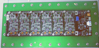
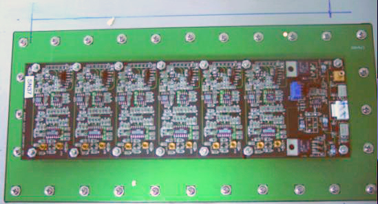
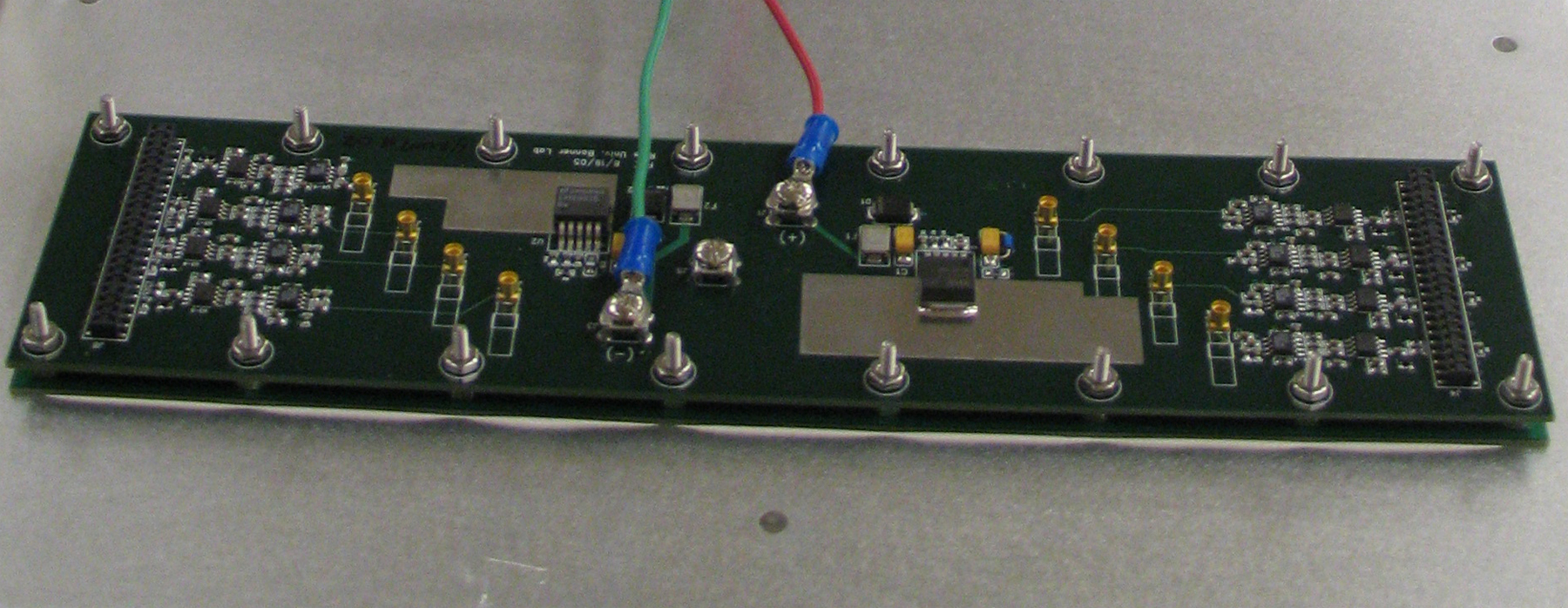
Electronics and DAQ Readout: FEE Readout: In T963 experiment, two modules use different FEE boards. The FEE of MODULE #1 is shown in Fig 1, in which 6 ADC and 6 TDC channels are included. This edition of FEE design was used by STAR TOFr tray R&D from 2002 to 2006. While MODULE #2 is equipped with a new edition that just 8 ADC without TDC channels are read-out, see Fig 2, which design has been tested at PHENIX. Every module has two pieces of FEE and two connector boards, all of which are fixed and set close to end of the tray boxes.
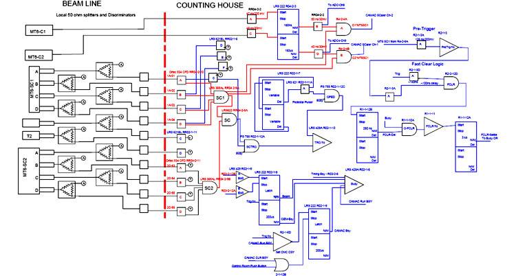
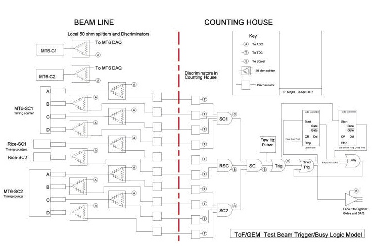
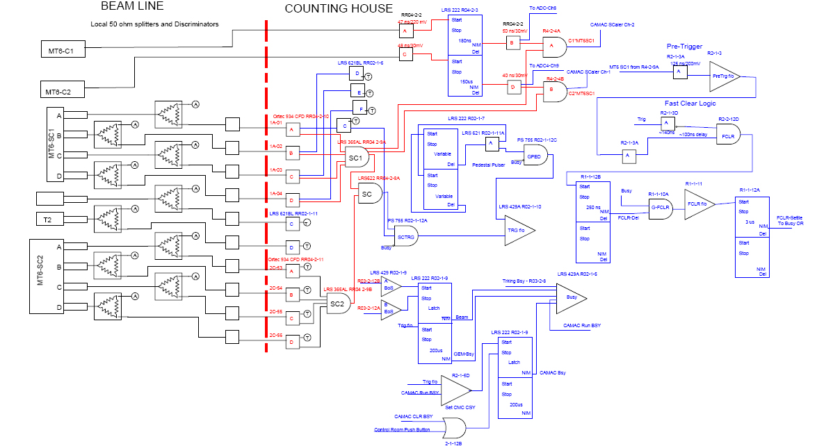
T963 Trigger System:
The trigger standard signal is given by the first PMT (upper&east) of
TOF1. The trigger logic can be found in Fig 3.
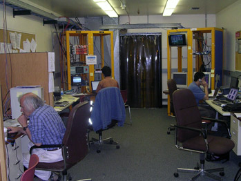
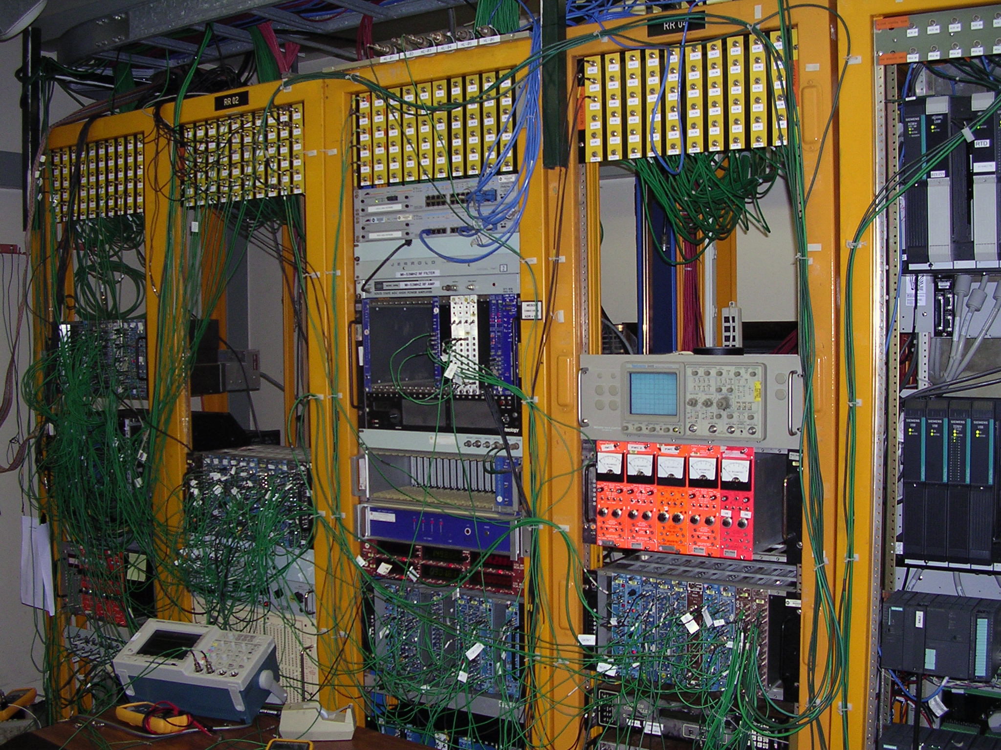
T963 DAQ System:
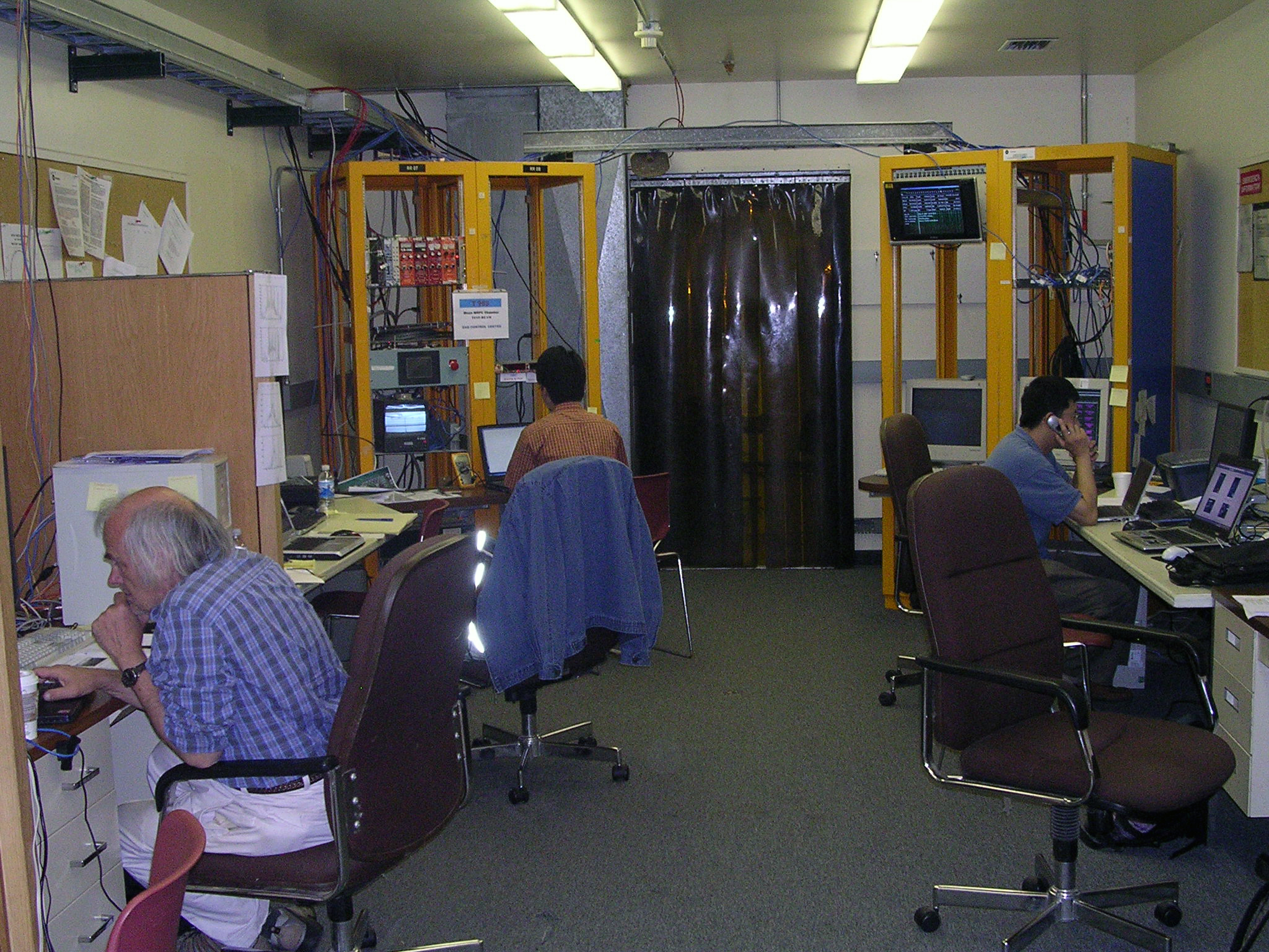
Fig 5&6 shows a view of T963 DAQ room and control center.
A CC-USB CAMAC Controller with USB-2 Interface is used in the main DAQ.
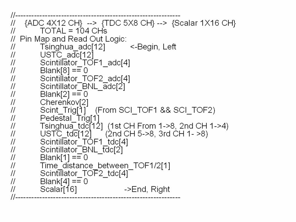
The DAQ readout data flow can be found in Fig 7.
|
||||||||||||||||||||||||||||||||||||||||||


