logo star

STAR SSD

- OPERATIONS for Detector Operators

Current Expert On call list, expert page

This page is dedicated to the operation of the SSD by detector operators. (You may wish to have a look at the expert page) An overview of the detector is available on the SSD section of the STAR NIM paper.

1 Guidelines for run 7
2 Launch the SSD Slow Control
3 How to turn ON the SSD and check it's ready
4 How to turn OFF the SSD
5 Problem solving
6 Description of the SSD Slow Control interface
7 The SSD Cooling system
8 The SSD and the interlocks


Legend

Important things are in bold characters.
Commands to be used at the Unix or VxWorks prompt are in italic blue.
MEDM (slow control) buttons are in bold green.


1 Guidelines for run 7

This year the cooling seems to be less efficient and this affect ladders 2, 3, 10, 13, 20 for which high voltages trip may occur. For this reason, ALL THE POWER SUPPLIES SHOULD BE SWITCHED OFF BETWEEN TWO FILLS, even for 30 minutes. This will help to cool down the detector.

  1. Before dump :
  2. After dump (no beam) :
  3. When beam cogged :


2 Launch the SSD Slow Control

The linux box ch3linux.starp.bnl.gov is the main machine for operating the SSD. The user should be logged on this machine under the login name "ssd". Ask the shift leader for the password. The core of the system is a VME board (ssdvme.starp.bnl.gov) running epics under VxWorks installed in the SSD rack on the South platform. The main window of the SSD slow control allows to bring the SSD ON in few clicks.

If absent, one can open the main SSD slow control GUI by typing in any ch3linux terminal : ssdsc
See the section 6 of this document for a description of the SSD slow interface.

During the SSD initialization, it is useful (but not necessary) to have a connection to the VME board to check for error messages. A serial link can be established by typing in any ch3linux terminal : vmeserie
This link is unique, so one has to make sure that one is not up already. If the serial link has not been started directly from the ch3linux station itself do ps -fu ssd | grep 'telnet' to identify and kill the process associated to this old link (kill -9 <process_pid>).


3 How to turn ON the SSD and check it's ready

This section lists the few steps/checks one has to go through to initialize the SSD.
    1. Make sure the SSD air cooling system is ON by checking the pressure at the Air Pressure box, green is ok.
      • if there is no information available check the status of the SVT Slow Control (which monitors the Air Pressure box), if OFF, ask the shift leader permission to turn it ON.
      if there is no information or in any doubt about the cooling system, if the SSD is OFF : DO NOT TURN the SSD ON, if the SSD is ON : Turn it OFF (see How to turn OFF the SSD),
    2. Turn ON the SSD :
      • Click on the purple RDO ON button, the black blue LV ON button and the grey blue HV ON.
      7 lower squares indicating ladder LV and HV status (see Ladder status) should be green if succesfull.
    3. Make sure the SSD is in the "FULL CONTROL" mode. If not, click on Full Control to switch from the "Acquisition" mode to the "Full Control" mode.
    4. Start the initialization by clicking on Start SSD. The status bar should iteratively display the following messages:
      • "Checking Readout boards"
      • "Loading FPGA program" (if the codes are not loaded yet)
      • "Loading Front End parameters"
      • "Reading Costar chips"
      • "All ladders are ready"
      • "Acquisition mode"
      It takes ~5 minutes to get the full SSD initialized and ready to take data.
      • Check on the main panel that all the RDO boards and ladders have been successfully initialized (everything should be green, squares and letters see Ladder status). It may happen that some ladders are not correctly initialized at this stage. In that case, repeat this sequence the step 4.
      • Check that the readout boards are ready to take data (all indicators green on the Main Panel for all 4 RDO boards, see section 6).

The SSD is ready if:

  1. All the status buttons on the main slow control panel are green.
  2. The 3 power supplies (RDO, LV, HV) are ON.
  3. The SSD is in "Acquisition" mode.

If not, repeat steps 3) and 4) above: Full Control and Start SSD.


4 How to turn OFF the SSD

At the end of the data taking period or when the beam is not expected before several hours (during a long scheduled access for instance), one can turn OFF the SSD by simply turning OFF the 3 groups of power supply buttons (ladder LV, ladder HV, RDO LV).

For run 7, turn OFF systematically between fills even for only 30 minutes.


5 Problem solving

VME,   LV problem,   HV problem,   RDO board problem,   Unstable slow Control ,   DAQ  

5.0 Unstable behavior of the Slow Control

Basically, the LV information seems to be corrupted, one observed blinking yellow squares moving from ladder to other ladder. The SSD can not be part of the acquisition anymore.
  1. Stop the run, ask to take the SSD out from the acquisition while fixing it,
  2. Turn OFF the LV, HV and RDO,
  3. Click on the Expert button (top left, blue button),
  4. Click on Crates button (in the Power Supplies box),
  5. Power OFF the Crate 1 and Crate 2, wait 2 minutes, power ON,
  6. Turn ON the RDO, LV and HV,
  7. Click on Start SSD.
This should clear the problem,
  1. If not, repeat the procedure once more,
  2. In the expert Slow Control, click on the (small) pink button and click on SysReset, then 6 and 7.
If this doesn't solve the problem, call the expert.

5.1 White squares in the Slow Control : connection lost with the VME board

When the connection with the SSD VME board is lost, all the slow control channels monitored turn into white. It can also happen that the system get frozen or respond badly to a slow control action. In that case, it may be necessary to reboot the VME cpu.
Like most of the STAR subsystems, the VME crate hosting the SSD vme board can be controlled by slow control via the CANBUS. The same procedure applies for the SSD to reboot the VME by this mean. Click on the Expert button to open the SSD expert window. Near the bottom, one can find the Icon made by the STAR Slow control group to access the VME crate information. Click on the pink small button to starts the VME crate panel and click on the SysReset button.

5.2 Yellow or red alarm in the Low Voltage ?

The problem mentioned here should be much less frequent during run VI since the power supplies have been “fixed” against it during summer 2005. Sometimes it happens that a ladder is showing a LV problem. Two kinds of problems have been seen so far :
  1. A ladder has lost its bias. In that case the current consumption on one or all the LV channels is zero or close to zero. Usually the -2V current is below the lower alarm limit and a yellow square should appear in the ladder status window. At best, only the FEE chips of that ladder must be reinitialised.
  2. A power channel has triped. The "internal trip" square in the channel should be red (see the section 14 on the SSD ladders status). In that case, the ladder is cleary lost and must be initialised again. This bias trip can also affect the adc and control boards themselve. In such case, these board can loose their FPGA code and thus it must be reloaded.

Moreover if nothing is done, in both cases, it is probable that the pedestal for that ladder will move out of the desired range and will not be well suppressed. The occupancy for that ladder will be increase and will significantly increase the SSD dead time. The procedures to fix these problems are the following :

  1. Yellow ALARM : Bias parameter lost
    1. Stop the run, ask to take out the SSD from the acquisition
    2. Switch to the Full Control mode
    3. Click on the Update button which should reload the bias parameters in the FEE chips. This should solve the problem.
    4. If the steps above do not solve the problem or trigger more problems, power cycle the SSD (by switching OFF and ON the LV and RDO V) and click on Start SSD.
    5. If the SSD is not back in a normal state, click on the Expert button, Click on the pink small button to starts the VME crate panel and click on the SysReset button (this takes ~3 min), turn the SSD ON again and start SSD (see section 3).
  2. Red ALARM : Power channel trip
    1. Switch to the Full Control mode
    2. Open the Expert slow control window
    3. Click on the corresponding ladder number to bring the expert window dedicated to the ladder.
    4. On the right side of this window, click on the rectangle (probably red) of the corresponding power channel to open the expert power channel window.
    5. Power cycle the channel by clicking on the OFF then ON button.
    6. If the internal trip is cleared go to the step j.
    7. If the internal trip is not cleared, note the current voltage value and change it to 0.
    8. Repeat the step e
    9. Once the trip is cleared set the voltage value to its nominal value.
    10. Go back to the main expert window and click on the FPGA button of the correspoding RDO board to reload the codes in the FPGAs.
    11. Click on Start SSD to reinitialise the SSD.
    12. If the SSD is not back in a normal state, try first to power cycle all the power lines (by switching OFF and ON the LV and RDO V) and click on Start SSD.
    13. If again the SSD in not back in a normal mode, reboot the VME (section 5.1) and start from scratch (section 3).

5.3 HV problem on a ladder ?

It may happen that a high voltage channel trips and the corresponding Slow Control box get red. This is serious because without high voltage, the noise on the N side of this ladder will jump resulting into a large occupancy.

Try to power cycle the HV You will have to play with Expert window for that. Click the Expert button on the main panel to get the SSD Expert Operations window. Click now on the ladder number to open the ladder expert window, then click on the High Voltage part like displayed in section 6 to open the Expert Power Channel window. There you can switch the power OFF and ON. The channel may come back without trip, otherwise call the expert.

5.4 Problems with a RDO board ?

Several times during the Run V some problems appeared with a RDO board :

The procedure to fix these problems is the following :

  1. Power cycle the RDO power line (RDO OFF and ON buttons)
  2. Click on Start SSD to initialise the SSD
  3. If it does not clear the problems, reboot the VME board (see section 5.1)
  4. Start the SSD initialisation from scratch again (see section 3)

For the first kind of problems mentionned above, the two first steps must be useless since up to now, it is connected to a VxWorks task dedicated to the RDO board slow control which gets suspended for unknown reason. Jump the step c in that case.

5.5 DAQ

It can happened that the SSD has 100% of deadtime which hangs the DAQ. If this happens :
  1. Stop the run, ask to reboot the SSD in the Run Control, and start the acquisition,
  2. If it doesn't solve the problem, take a look at the Slow Control :
  3. If it doesn't solve the problem, take the SSD out of the acquisition and call the expert.


    6 Description of the SSD Slow Control interface

    Main Panel,   Ladder status,   RDO board status,   ,  

    6.1.Main Panel

    1. The main buttons:
      • Start SSD: start the full SSD initialization chain
      • Update: resume the initialization after a manual intervention
    2. The status bar: displays the current mode or various steps and error messages during the initialization
    3. The control buttons:
      • Full control: the SSD is in control mode. Mandatory for the initialization
      • Acquisition: the SSD is in acquisition mode. Mandatory to take data
      • Calibration: the SSD is in calibration mode. Useful to do gain calibration. Not necessary to take pedestal data. This require expert knowledge so far.
    4. The power supply panel: Allows to turn ON/OFF the ladder LV, ladder HV and the RDO boards LV. They all must be ON during data taking. The HV can be turned OFF in some cases (see section 4).
    5. The SSD cooling status : Gives the compressed air pressure before the vortecs. It should be around 115 psi (± 10 psi, see section 7).
    6. The readout board X status: Gives a summary of the readout board status. Clicking on the More button brings up the RDO summary panel (see section 6.3).
    7. The ladder X status : Gives a summary of the ladder status. See the next section 6.2 for a more detailed explanation.
    8. The expert button: brings up the SSD expert panel. Should be used by the operator only upon request from one SSD expert or to Reset the VME crate (see section 5.1).

    6.2 The SSD Ladder status

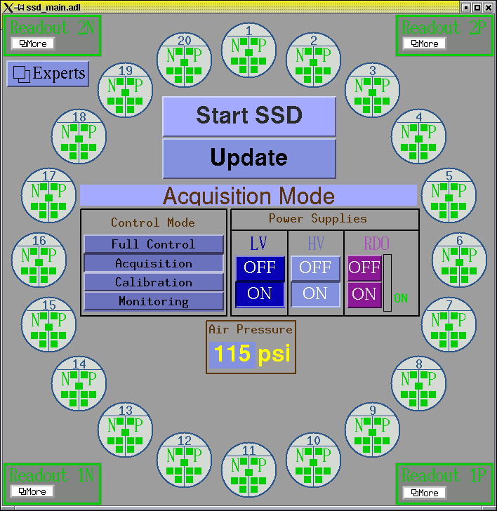
    On the main SSD slow control panel, the monitored information on a ladder is summarized in the circle above. The information is symmetrically displayed for the N-side (left) and the P-side (right).

    This information is detailed a bit more in the ladder summary panel below. One can open this panel by clicking on the ladder Number in the small gray circle above.
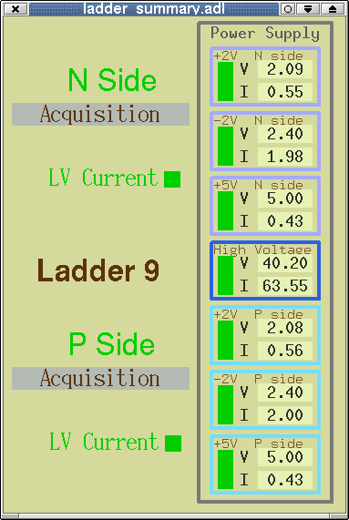
    The nominal voltage setting and the average reading values are given in the following table :
    Power line Voltage setting (V) Voltage reading (V) Current reading (A)
    LV (+2Volts) 2,1 2,09 0,5
    LV (-2Volts) 2,4 2,4 2,0
    LV (+5Volts) 5,0 5,0 0,4
    HV (+50Volts) 50,0 50,0 1,00E-04
    These values are indicative especially the current reading. Some variations of about 10-20% is usually observed between ladders.
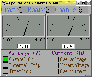
    Clicking on the status rectangle of a given LV or HV line will open the power channel summary window for that channel. The window is shown on the right:

    6.3. The SSD readout status

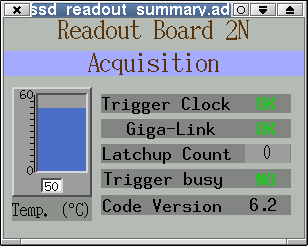
    The readout summary panel for each RDO board can be opened by clicking on the More buttons on the main panel. This panel is shown on the left picture.
    The RDO is ready to take data if :
    • The board is in the "Acquisition mode".
    • Both the "Trigger Clock" and "Giga-link" channels show a green "OK".
    • The temperature on the boards should also be stabilized between 40 and 60°C.


    7 The SSD Cooling system

    The SSD ladders and the readout boards are air-cooled. The air is taken from the TPC-IFC, pulled through the ladders, the RDO boards and released to the WAH. Four vortecs (transvector airflow amplifier) installed on the Pole Tips use 7 bars compressed air and induce an air flow of the order of 1 liter/s in the ladders and the RDO boxes. A solenoid valve controls the compressed air flow before the vortecs. This valve is slow controlled by the SVT system installed on the North platform.

    The pressure of the compressed air is monitored and displayed on the main SSD panel. Its value should be around 115 psi (±10 psi). The temperature on the SSD readout boards is also monitored by the Slow control. After the SSD is initialized, the average temperature is around 50ºC on these boards.

    One should keep in mindthat the valve is closed by default (especially after a power failure) and its status should be checked first in case of troubles with the SSD cooling system. The valve is controlled on the channel 8 of the SVT Power Network Switch. Consult the SVT Operation guide for the procedure to check its status or go the expert page.


    8 The SSD and the interlocks

    The SSD interlock system is closely linked to the SGIS. It uses a custom-made relay driven system integrated in the SSD slow control crate located on the STAR south platform. The SSD power supplies can be turn on only if the IFC permissive (from SGIS) is granted. The SSD slow control window does not show the status of the interlock signal yet but since the permissive used by the SSD is commonly used by the other subsystems one can check that it is granted on the other slow control windows.

    ssd back button the SSD team

    Last updated by vnt on