Goal: produce relative SMD gains
Goal: produce absolute SMD gains
  // MIP cut .........
  float thrMipSmdE=0.5/1000.;
  int emptyStripCount=7;
  float offCenter=0.7; // fiducial area of tower =offCenter^2
  float twMipRelEneLow=0.5, twMipRelEneHigh=2.;
  int thrMipPresAdc=12; // thres over pedestal for pre/post
Iteration 1c , SMD thrs=15 ADC over ped, OUTPUT:
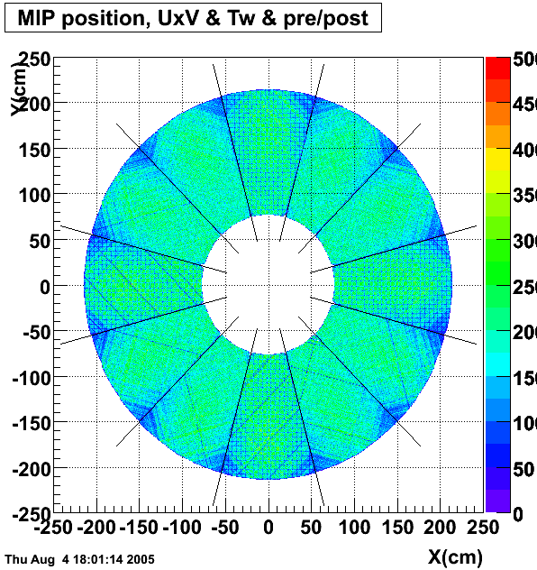
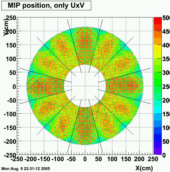
Only UxV condition
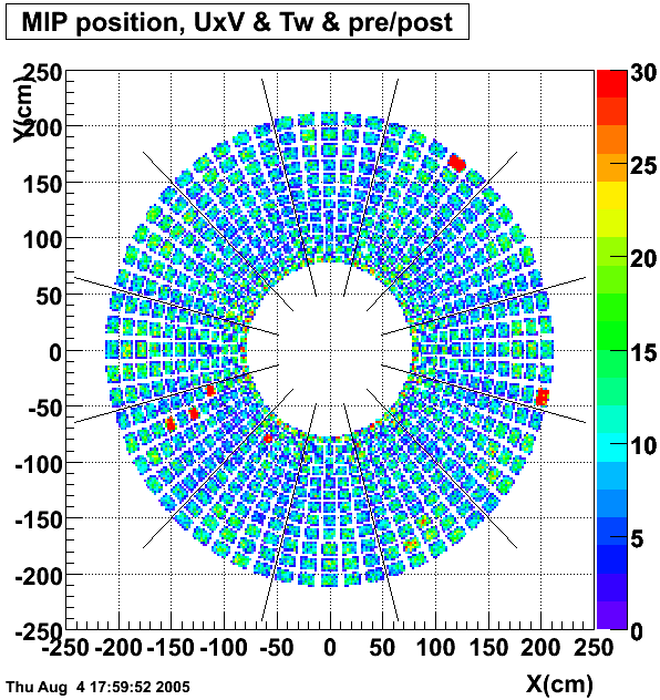
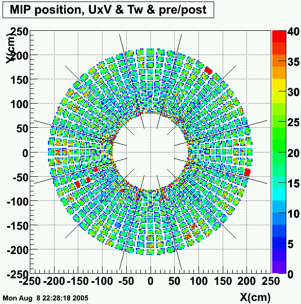
Also pre/post/tw cuts included
* Landau fit for each group of strips: PDF
* Mean of Landau fit for each plane: PDF, red=average, blue=goal=1.3 MeV
(sum over 12 consecutive pairs of strips, 24 groups per SMD plane)
Iteration 1d SMD thrs=0.3 MeV, OUTPUT not posted, MIP response is at 1.2 MeV instead of 1.4 MeV seen with ADCthr>15. The peaks in energy sums for large strip ID are even more pronounce.
Iteration 1e SMD thrs=0.5 MeV, OUTPUT:
Oulu UxV condition
Also pre/post/tw cuts included
* Landau fit for each groupe of strips: PDF, green=goal=1.3 MeV, red=Landau fit
* Mean of Landau fit for each plane: PDF, red=average, blue=goal=1.3 MeV
(sum over 12 consecutive pairs of strips, 24 groups per SMD plane)
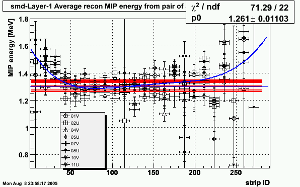
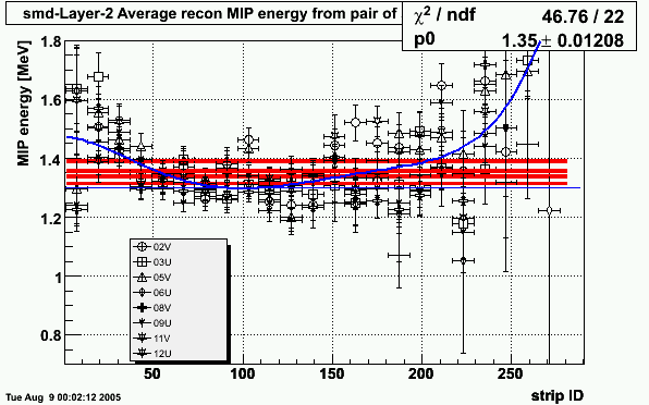
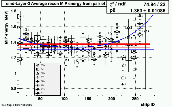
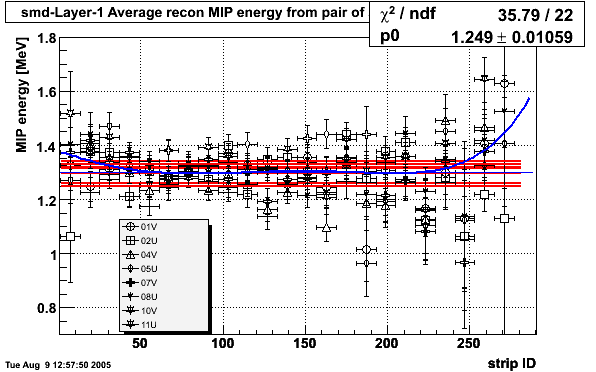
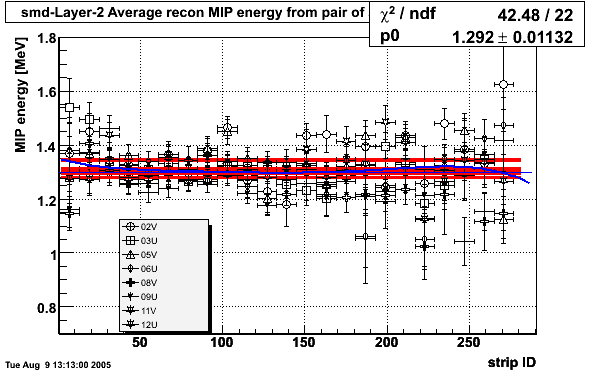
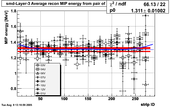
Goal: average MIP correction for SMD over many plains
Method: MIP corrections were averaged over 8 SMD plains in each layer, outliers dropped, low degree polynomial fitted, old smd gains from slopes corrected by the ratio of smooth fit function (blue) to 1.3 MeV.
* SMD-layer-1 (closest to IP)
* SMD-layer-2
* SMD-layer-3
Used script reCalSmd.C
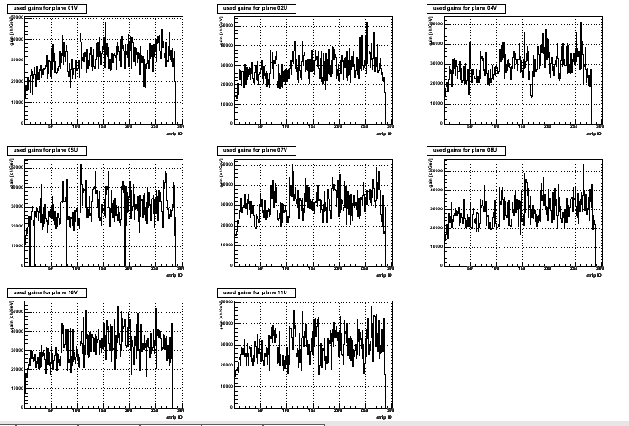
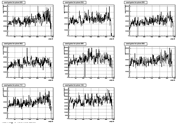
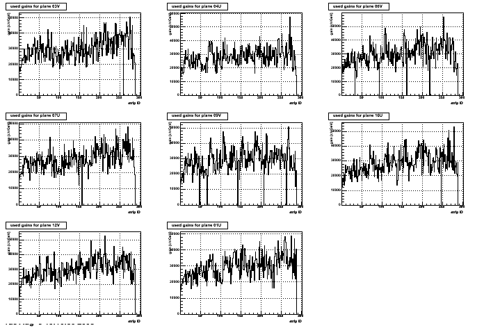
X-axis =strip ID, one plot per SMD plain.
Y-axis shows gains in ch/GeV of deposited energy for normal incident MIP traversing a strip through the apex. Grid is at 10Kch/GeV, 20K, etc. Energy/GeV = (rawAdc-ped)/gain;
* SMD-layer-1 (closest to IP), sectors: 01V , 02U , 04V , 05U , 07V , 08U , 10V , 11U
* SMD-layer-2 , sectors: 02V , 03U , 05V , 06U , 08V , 09U , 11V , 12U
* SMD-layer-3 , sectors: 03V , 04U , 06V , 07U , 09V , 10U , 12V , 01U
Goal: Verify absolute SMD gains
Method: reco the same events once more and calculate next iteration of corrections:
* SMD-layer-1 (closest to IP)
* SMD-layer-2
* SMD-layer-3
Note, the SMD correction from iteration 2 were NOT used.
SMD CALIBRATION IS DONE