


Next: Discrete Wavelet Transform power
Up: Cross-talk analysis
Previous: Cross-talk correction for the
Contents
Kopytine's homepage
The double differential multiplicity distribution
Figure 6.10:
Double differential multiplicity distributions of charged particles
plotted as a function of azimuthal angle  (with different symbols representing different rings)
and of pseudorapidity
(with different symbols representing different rings)
and of pseudorapidity  (with different symbols representing different sectors).
The and are in the aligned coordinates.
(with different symbols representing different sectors).
The and are in the aligned coordinates.
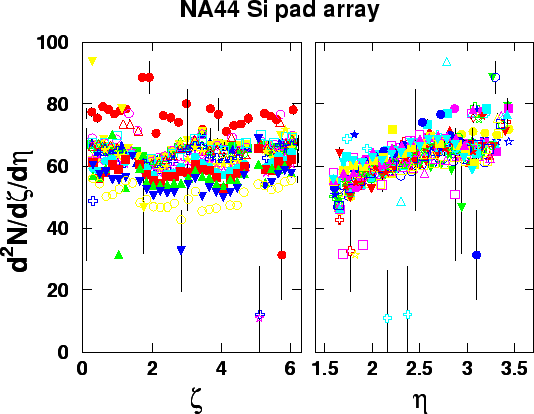 |
The double differential multiplicity data (Fig. 6.10)
illustrate the quality
of the detector operation,
calibrations (Section 6.3),
geometrical alignment and Jacobian correction (Section 6.4).
The data set is composed of two pieces, obtained by switching
the magnetic field polarity:
run 3192
is used for sectors 9 to 24 (range of
 );
run 3151
is used for sectors 1 to 8 and 25 to 32
(range of
);
run 3151
is used for sectors 1 to 8 and 25 to 32
(range of
 and
and
 ).
The reason to disregard one side of the detector is additional
occupancy due to
).
The reason to disregard one side of the detector is additional
occupancy due to  -electrons,
as was explained in section
6.2.
Figure 6.10 demonstrates the quality of alignment as well,
since the
and along the horizontal axes are the aligned coordinates.
Any geometrical offset of the detector makes acceptances of different pads non-equal
and dependent on the pad position.
The acceptance of each pad has been calculated in the aligned coordinates,
and the
-electrons,
as was explained in section
6.2.
Figure 6.10 demonstrates the quality of alignment as well,
since the
and along the horizontal axes are the aligned coordinates.
Any geometrical offset of the detector makes acceptances of different pads non-equal
and dependent on the pad position.
The acceptance of each pad has been calculated in the aligned coordinates,
and the
 uses the actual acceptances
  .
The shape of the dependence of
.
The shape of the dependence of
 (left panel of Fig. 6.10) is flat
as it should be for an event ensemble with no reaction plane selection.
The dependence (right panel of Fig. 6.10) shows
increasing multiplicity towards midrapidity,
(left panel of Fig. 6.10) is flat
as it should be for an event ensemble with no reaction plane selection.
The dependence (right panel of Fig. 6.10) shows
increasing multiplicity towards midrapidity,
![[*]](file:/usr/local/lib/latex2html/icons/footnote.gif) as is expected.
The absolute value of
as is expected.
The absolute value of
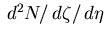 includes a correction
for the channel cross-talk, discussed in Subsection 6.5.5.
includes a correction
for the channel cross-talk, discussed in Subsection 6.5.5.
Next: Discrete Wavelet Transform power
Up: Cross-talk analysis
Previous: Cross-talk correction for the
Contents
Mikhail Kopytine
2001-08-09